Category: JEE

  • Projectile motion

    Projectile motion

    Projectile motion

    Projectile given horizontal projection and projectile given angular projection

    In this topic we will discuss about projectile given horizontal and projectile given angular projection. And we will derive the expressions for equation of trajectory, time of flight , vertical height , horizontal range and velocity of projectile at any time .

    Projectile motion-

    When a body has given some initial velocity , and body allowed to move in two dimensional motion under the action of gravitational force only ( i.e. there is no any external force acting on the body ) such kind of motion of the body is called projectile motion .

    • Important things to know about the projectile motion- projectile moves with constant horizontal velocity, there are no any external force it means there is no acceleration or retardation in horizontal motion.
    • The vertical velocity changes with time i.e. increases or decreases when moves downward or upward direction respectively under the gravitational acceleration.
    • There is no air resistance ( practically it is not possible in earth surrounding , but considered)
    • The magnitude of acceleration due to gravity remain constant at every point it doesn’t changes even at height or depth.
    • Projectile given horizontal projection-
    • HORIZONTAL PROJECTION
      HORIZONTAL PROJECTION

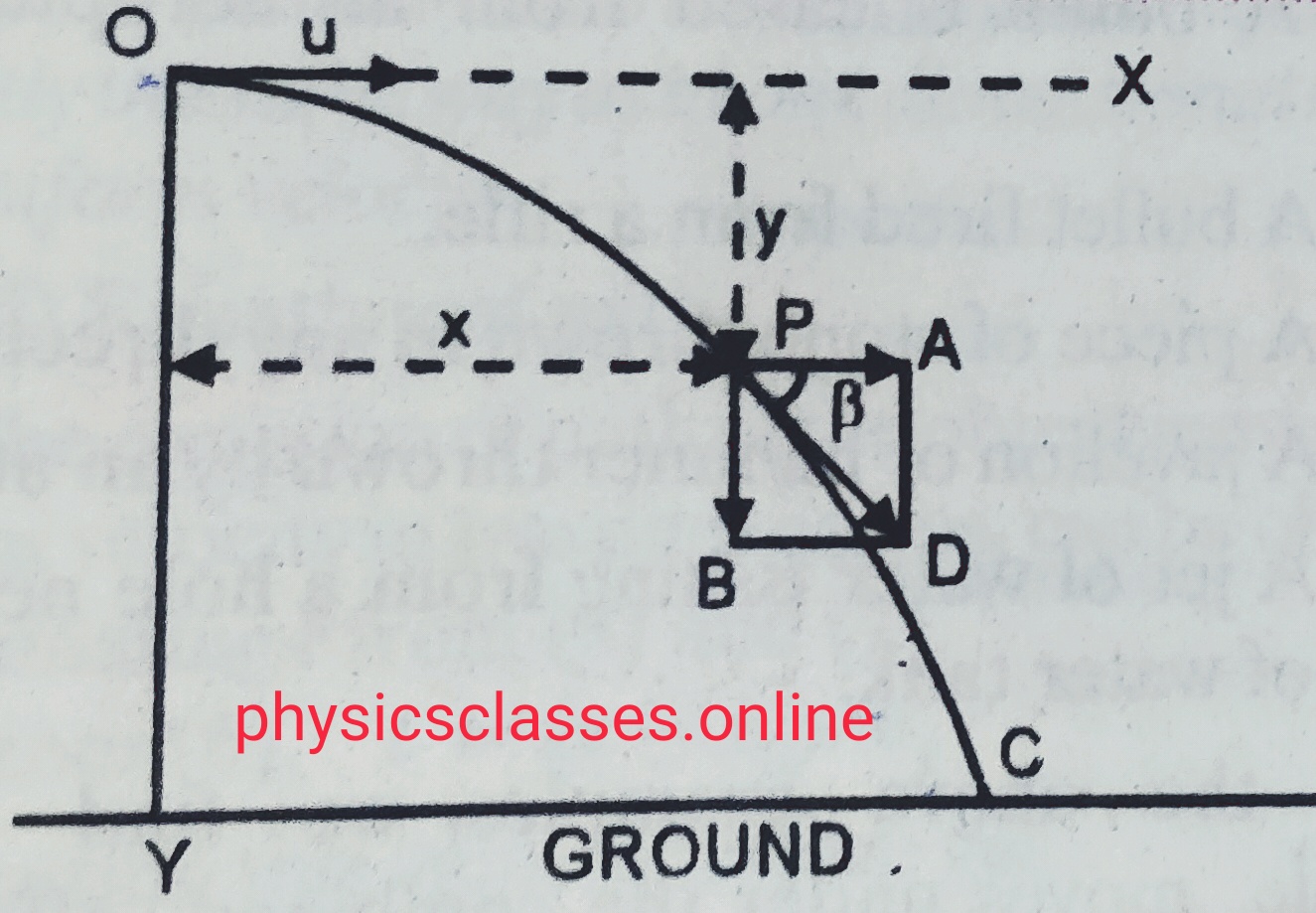
    Suppose OX a horizontal line is parallel to the ground and oy is vertical height. A body is projected with velocity  u in horizontal direction ,

    so, ux = u and uy = o

    Let t is the time taken by the body to reach from initial point O to final point C ( as shown in fig. ) then ,    horizontal distance X = ux x t  = u x t

    so  t= x /u

    Again for vertical motion  Y = uyt + ½ gt2 = 0 + ½ gt2

    y = ½ g (X/u)2

    or , Y = ½ g X2/u2……………………..(i) This the equation of trajectory which is equation of parabola , then we can say path followed the projectile is parabolic .


    Time of flight (T)  – It is the time taken by the projectile to reach from initial to final position , let T is the time of flight and H is the height ,

    Then,  from equation of motion  Y = uy + ½ gT2

    ( but uy =0)

    so, Y= ½ g T2

    or ,  T = √2H/g ………………(ii)

    Horizontal range (R)   – It is the horizontal distance covered by the projectile during its flight . Since there is no acceleration in horizontal direction.

    So , distance = speed x time

    X = R = u x T = u √2H/g .

    Velocity of the projectile at any time ‘t’ –  As shown in fig. at point p  , there are are two components of the velocity ,  vx and vy along horizontal and vertical direction respectively , then , v =  √(vx)2 + (vy)2

    Or , v = √ u2 +(gt)2 ( since , vx = u and vy = gt )

    Let v makes an angle β with the horizontal then , tanβ = vy/vx

    Or , tanβ = gt/u .

    Or , β = tan-1(gt/u) with the horizontal.

    TO SEE THE VIDEO ON PROJECTILE GIVEN HORIZONTAL PROJECTION CLICK HERE-

    Projectile given angular projection- 

    ANGULAR PROJECTION
    ANGULAR PROJECTION

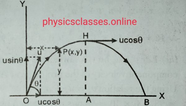
    Suppose a projectile is projected at an angle θ with horizontal , and velocity given to the projectile is ‘u’ . OX and OY are the horizontal and vertical axis respectively . Then the component of velocity along OX and OY are respectively u cosθ  and  u sinθ .


    Equation of trajectory-  let  ‘t’ is the time taken by the projectile to reach from point O to point B as shown in fig.

    Then horizontal distance X = u cosθ x t ,

    Or, t=x/ucosθ

    But for vertical motion ,  y= uyt + ½ g t2

    Putting the  value of time in the above equation we get ,

    Y = usinθ .( x/ucosθ)   + ½ g ( x2/ u2 cos2θ) .

    Or , y=  x tanθ + ½ g (x2/u2 cos2θ) …………………….this is the equation of trajectory , which is parabolic . Hence we can say path followed by the projectile is parabolic .


    Time of flight (T) –     It is the total time taken by the projectile to reach from initial position to the final position .   Total time of flight ( T) =  ta ( time of ascent) + td (time of descent ) .

    [       Time of ascent is the time taken by the projectile to reach to max. height by the projectile. And time of descent is the time taken by the projectile to reach from highest position to the point on the ground .]

    As we know , for ascending motion , v = uy – gta

    But at highest point v=0 , so , 0= u sinθ – g ta

    g ta = u sinθ

    ta = u sinθ/g ;

    Hence, Time of flight  , T = 2 ta = 2u sinθ/g ……………eq.


    maximum height(H) – It is the maximum vertical height attained by the projectile above the point of projection during its flight .

    from 3rd equation of motion v2 -u2 =2as ;

    0 – u2sin2θ = – 2gH

    H = u2sin2θ/2g ……………………eq.

    Horizontal range(H) –  It is the displacement of the projectile  between point of projection and point of hitting the ground .

    Since there is no acceleration in horizontal direction and hence

    X= R = u cosθ x T = u cosθ . 2u sinθ/g = u2 2sinθ cosθ/g  = u2 sin2θ /g ;

    Range R = u2 sin2θ /g ………………eq.

    TO SEE THE COMPLETE VIDEO ON PROJECTILE GIVEN HORIZONTAL PROJECTION CLICK HERE-

    Velocity of projectile at any time –

    VELOCITY OF PROJECTILE AT ANY INSTANT
    VELOCITY OF PROJECTILE AT ANY INSTANT

    At ant time the velocity has two components vx (velocity along x- axis) and vy (velocity along y-axis ). So at any time velocity v= √vx2 + vy2

                                                                                           v = √ [u2 cos2 θ + (u sinθ – gt)2 ].

    Or , v = √ (u2 + g2t2-2ugt sinθ ).

    Let β be the angle of resultant velocity with horizontal direction then ,

    Tanβ = (u sinθ-gt) / (ucosθ)

    [ ***** note- question based on the projectile may be asked to find the all equations but angle of projection is θ with the vertical instead of  horizontal in that case  , at the place of sinθ take cosθ and vice-versa .*******]
  • PHASOR DIAGRAM

    PHASOR DIAGRAM

    PHASOR DIAGRAM-

    PHASORS AND PHASOR DIAGRAM-

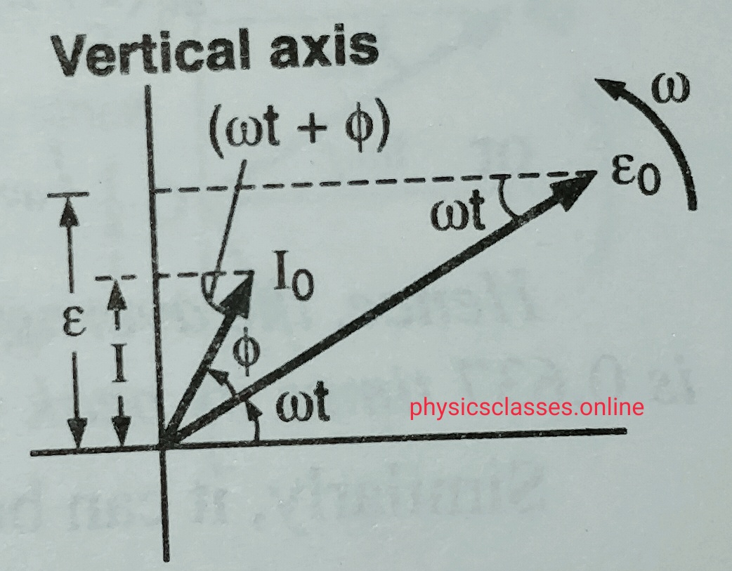
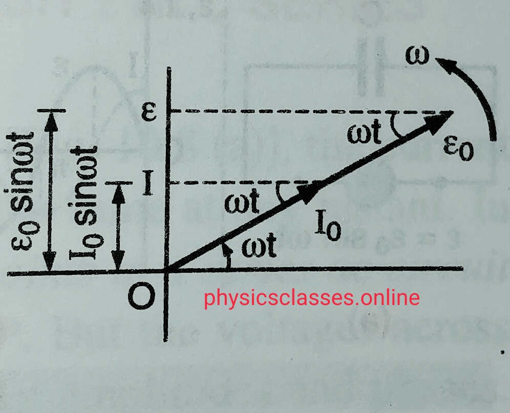
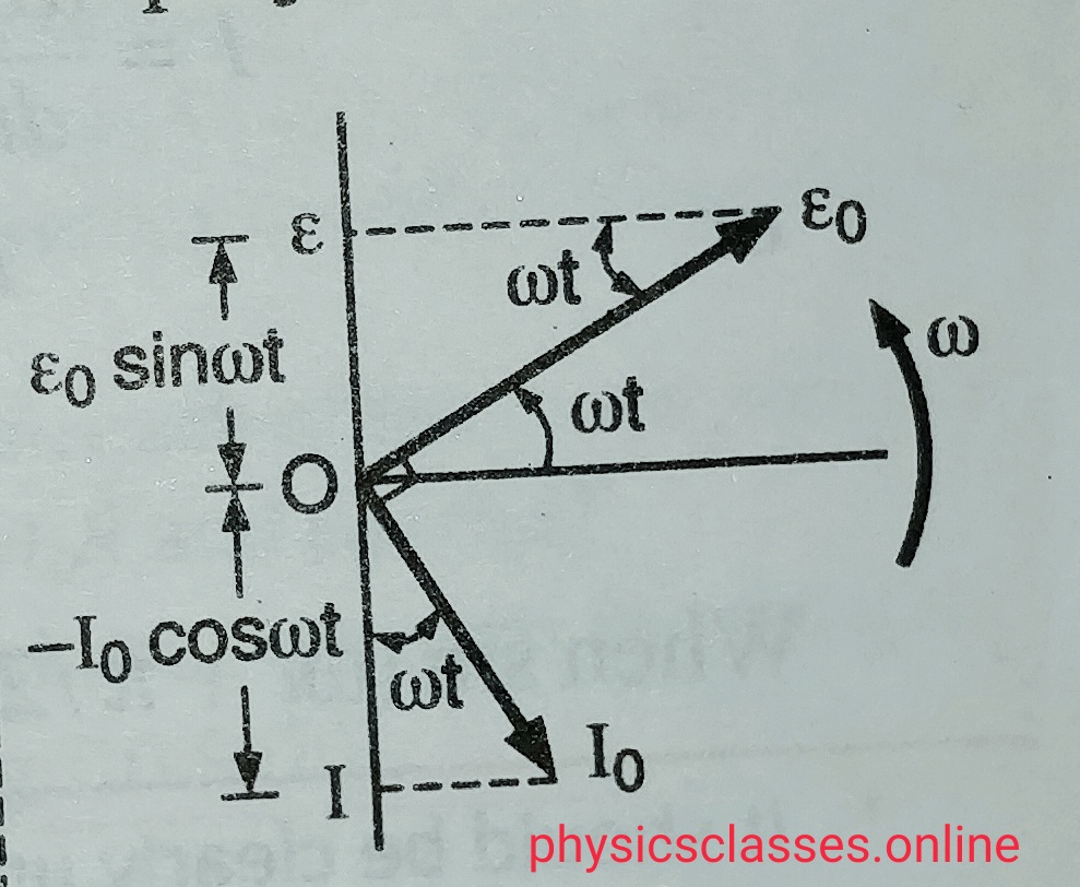
    The co-planar vectors which represents sinusoidal time varying quantities like alternating current or alternating voltage are known as phasor and the graphical representation of these quantities for the ac circuit is known as phasor diagram.

    In another words we can say when AC or alternating voltage  represented as rotating vectors in a graph is  known as phasor diagram .

    • Phasors are represented by the arrows rotating anticlockwise .
    • The length of the arrow represent the peak current or peak voltage.
    • Phasor diagram represents the phase relation between alternating current and voltage

    Representation of phasor diagram for an ac source-

    PHASOR DIAGRAM1
    PHASOR DIAGRAM-1


    Phasor diagram when ac circuit containing only resistance –

    PHASOR DIAGRAM -2
    PHASOR DIAGRAM -2

     Phasor diagram when ac circuit containing only capacitor-

    PHASOR DIAGRAM -3
    PHASOR DIAGRAM -3


    Phasor diagram when ac circuit containing only inductor-

    PHASOR DIAGRAM -4
    PHASOR DIAGRAM -4


  • What do you mean by Relative velocity ?

    What do you mean by Relative velocity ?

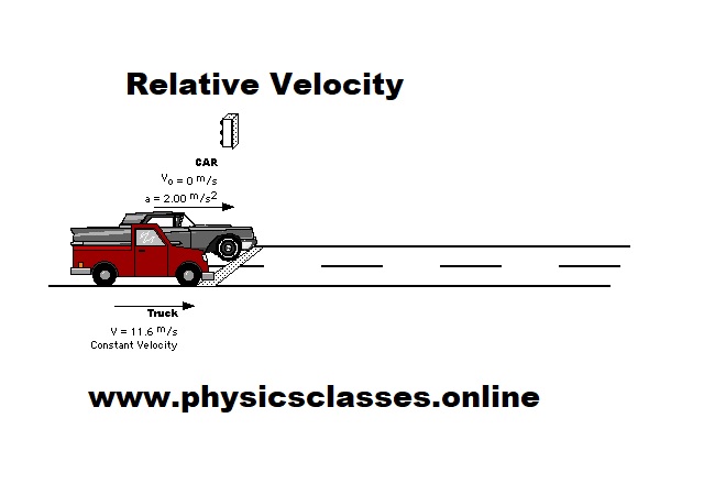
    This topic will discuss about the velocity of an object with respect to another object. In this article you will learn Relative Velocity Analysis  in both forms text and video as well.

     Relative velocity of one object with respect to another is the velocity with which one object moves with respect to another object .When two objects A and B are moving with different velocities , then the velocity of one object A with respect to another object B is called relative velocity of object A with respect to object B , hence relative velocity is defined as the time rate of change of relative position of one object with respect to another.

    • Watch Relative Velocity Analysis Video :

    Expression for the relative velocities – Suppose two objects A and B moving with uniform velocities VA and VB respectively along parallel straight line path in the

    (i) Same direction (I.e. angle between them is 00)  ;

    Relative velocity of A with respect to B = VA -(VB ) = VA -VB


    (ii) Opposite direction (I.e. angle between them is 1800)

    Relative velocity of A with respect to B = VA – (-VB ) = VA + VB

    To read or download complete topic of Relative velocity click here-


    Download QA for various chapters of Physics 


  • GRAPH

    GRAPH

    GRAPH

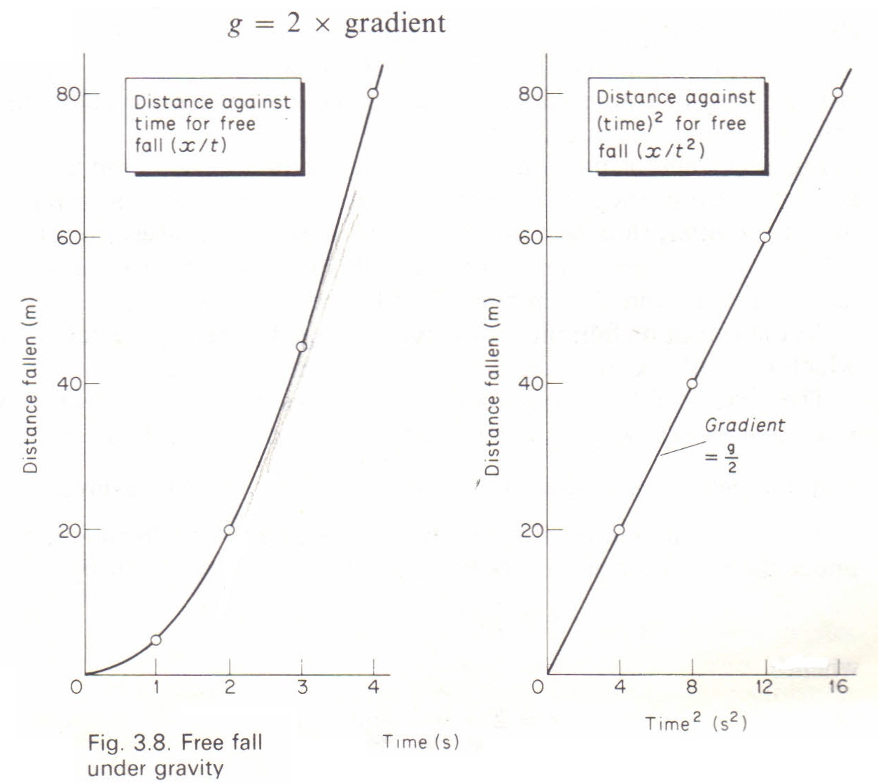
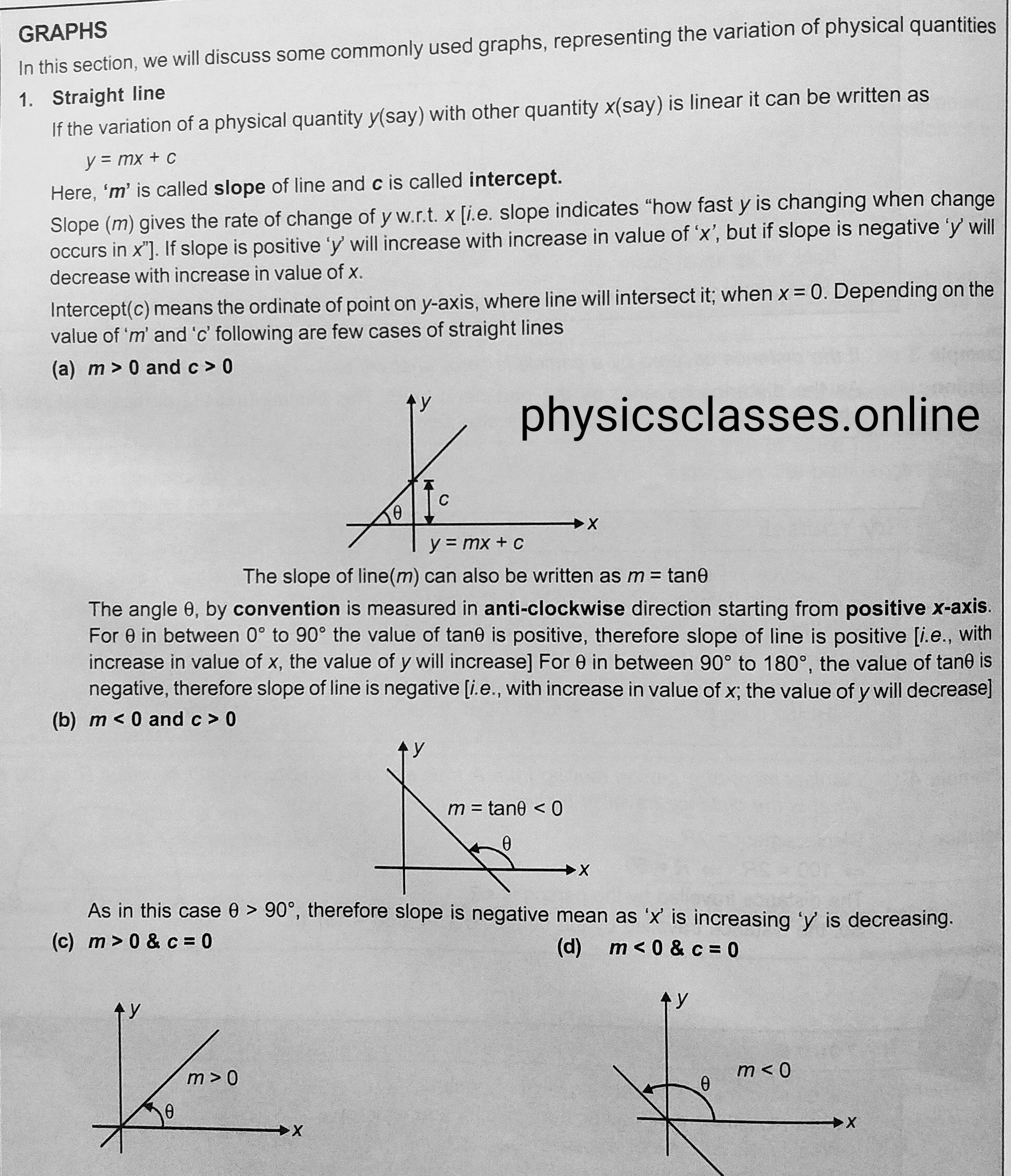
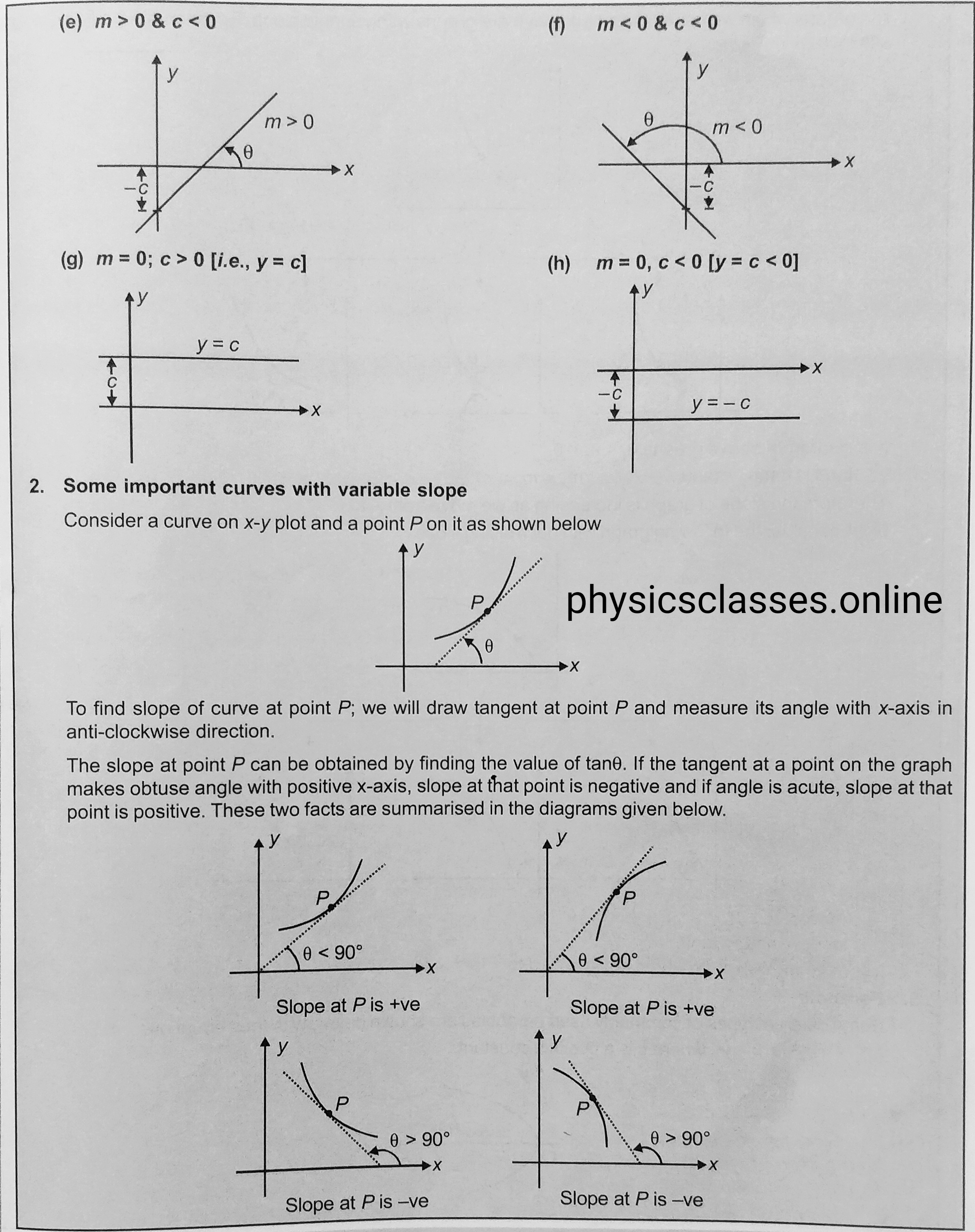
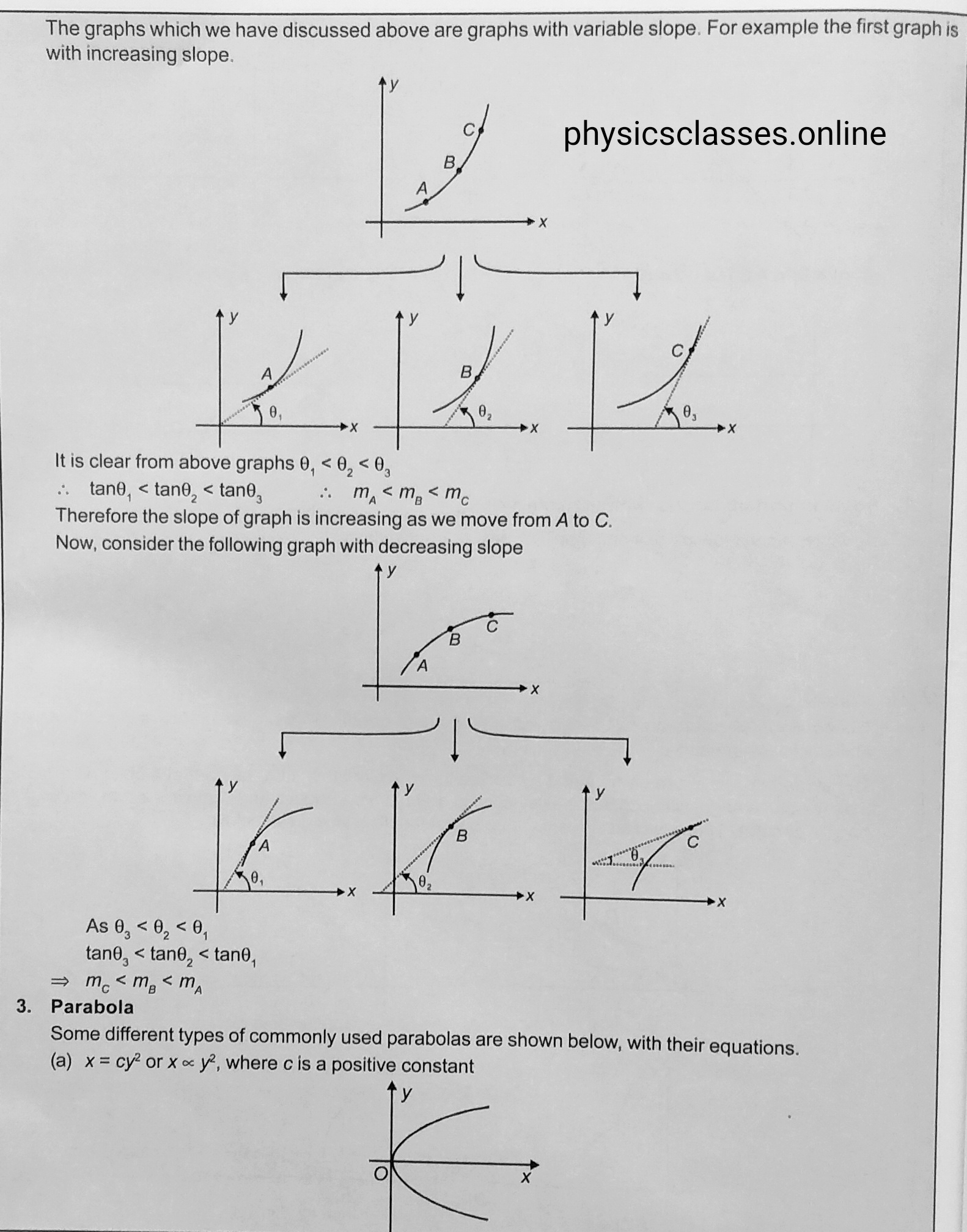
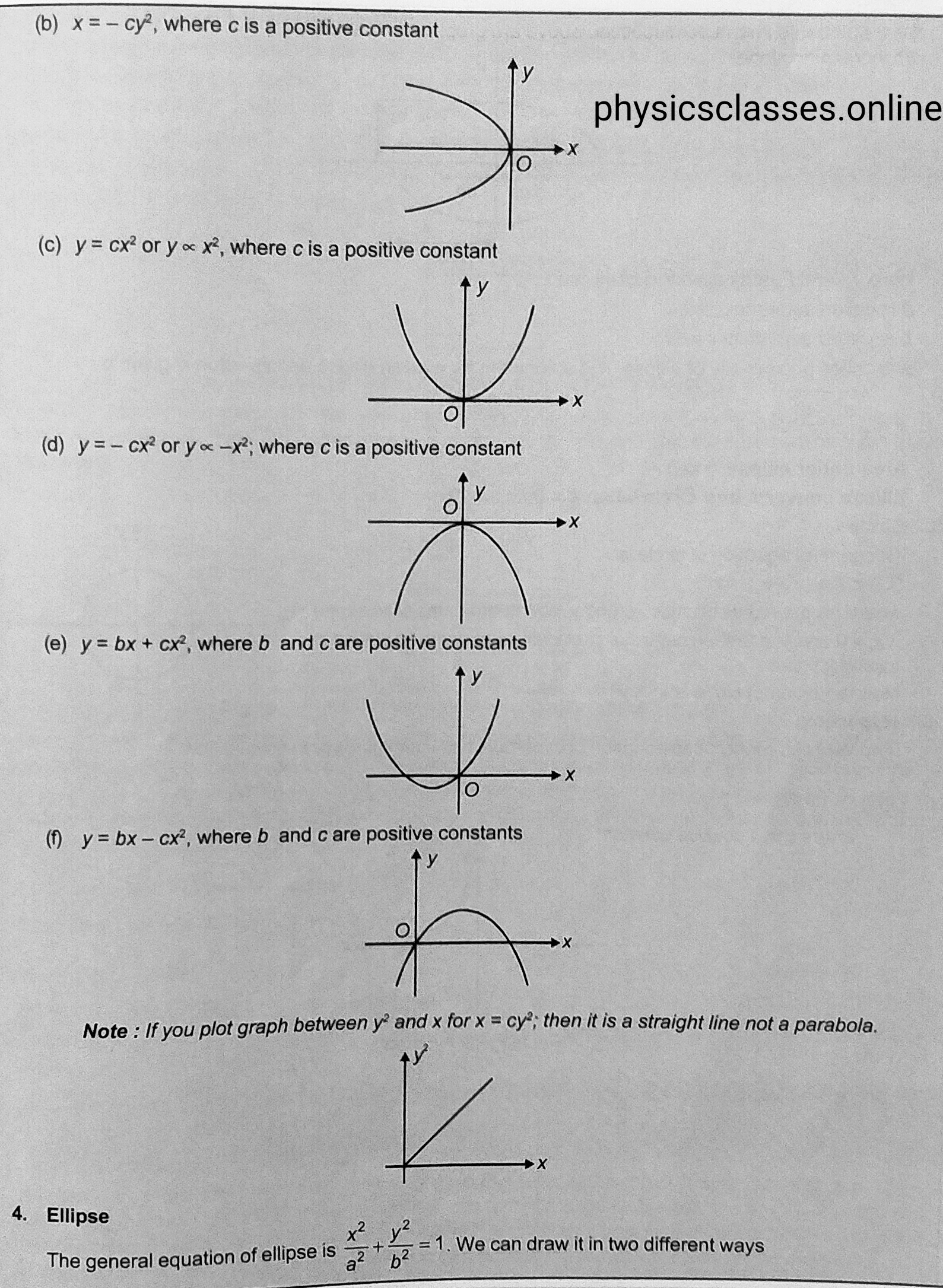
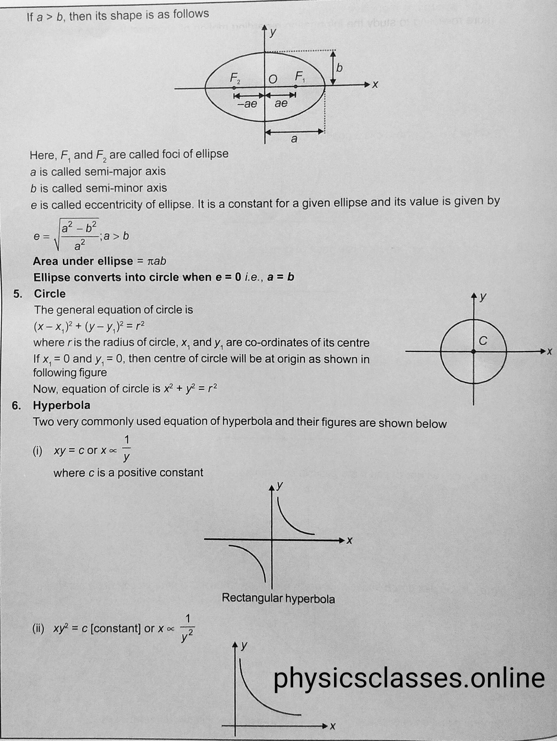
    In this post we will discuss about the graph , and how graphs makes to understand  the physics easily ?

    Graph-

    As we know it is not easy to study or understand the physics. Students who is taking interest in physics and want to understand the physics, it is necessary to improve your mathematics and most importantly graph, students who can’t solve the graphical questions will face lot of difficulties. So I am trying to provide some information/ knowledge for the students, so that students can understand the graphical questions easily. Now these days questions based on graph is important for every topics of physics specially the students who is appearing in the JEE/ NEET examination. Graph makes the calculation easier and it makes the topic to understand more easy. So every students must have to understand the graph and solve the questions based on it.

    Pg. -1

    peg 1 graph
    peg 1 graph

    Pg. -2

    peg 2
    peg 2

    Pg. – 3

    peg 3
    peg 3

    Pg. – 4

    peg 4
    peg 4


    Pg.-5

    peg 5
    peg 5


  • MOTION

    MOTION

    MOTION

    MOTION , THERE DIFFERENT TYPES, AND EQUATIONS OF MOTION .

    MOTION OF AN OBJECT


    Motion –

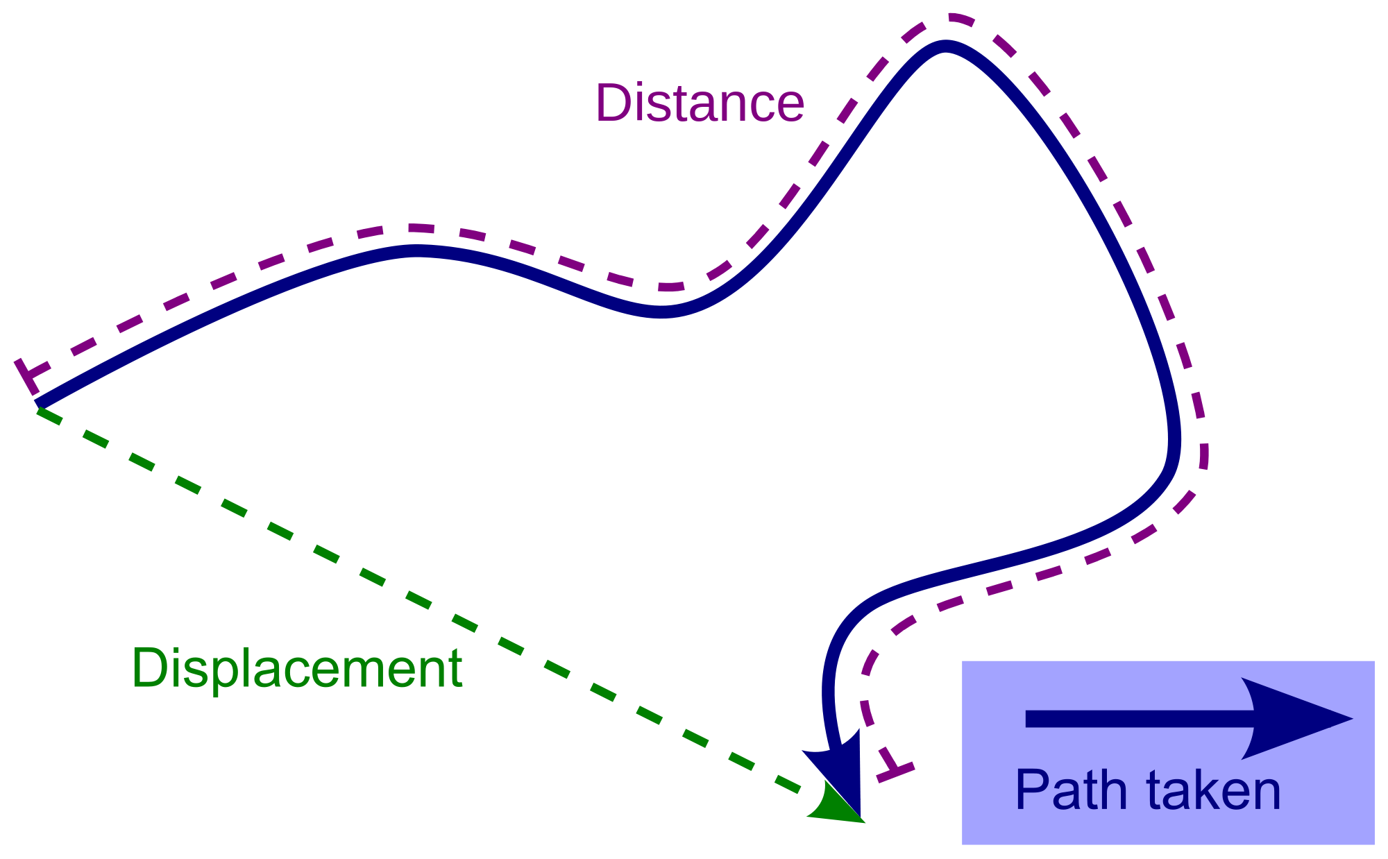
    Rest and Motion -An object is said to be in rest , if body does not change its position with time , with respect to surroundings . An object is said to be in motion , if body  changes its position with time , with respect to surroundings .

    Motion of the body can be of following type –

    • Rectilinear / Translatory motion – In rectilinear motion a point mass body moves along a straight line . but in translator motion a body which is not a point mass moves in a straight line path.


    • Circular or rotatory motion – In circular motion a point mass object moves on a circular path. But in rotatory motion a body which is not a point mass moves on a circular path .


    • Oscillatory or vibratory motion– oscillatory motion is a type of motion in which a body moves to and fro or back and forth repeatedly about a fixed point. If in the oscillatory motion, amplitude is very small then the motion of the body is said to be in vibratory motion.


    Motion in one , two and three dimensions-

    • One dimensional motion– The motion of a body is said to be in one dimensional if only one co-ordinate specify the position of the object in the given time. In such a motion body moves along a straight line
    • Two dimensional motion– The motion of a body is said to be in two dimensional if any two coordinate specify the motion of the body.
    • Three dimensional motion – The motion of a body said to be in three dimensional if all three coordinates specify the motion of the body . in such kind of motion body may cover a specific motion or irregular motion.


    UNIFORM AND NON-UNIFORM MOTION- 

    Uniform motion – If a body covers equal distance in equal interval of time then it is said the motion of a body is uniform .

    Some important features of the uniform motion is following-

    (a) For a uniform motion  along a straight line in a given direction , the distance and magnitude of the displacement remain the same .

    (b) The velocity in uniform motion doesn’t depend upon the time interval .

    (c)There is no need of force for an object to be in uniform motion .

    (d) The velocity in uniform motion is in dependent of choice of origin.

    (e) The average and instantaneous velocities have value in uniform motion.


    If the motion of the object is uniform the following formula is used to find the

    different– different physical quantities .


    Distance = speed x time ;    speed = distance / time


    Displacement = velocity x time ;   Velocity = displacement / time ;

    Average speed = total distance covered / total time taken .


    Average velocity = total displacement covered / total time taken


    V =  X2-X1 / t2-t1 .


    Non-uniform motion- An object is said to be in non-uniform motion if it covers unequal distance in equal interval of time ,or equal distance in unequal interval of time. The velocity of a body changes with time it may increase ( accelerated ) or decrease (deaccelerate) with time .

    Following are the important equations of motion– for uniformly accelerated motion

    • 1st of motion ( it is also known as velocity – time relation)- v = u + at ( Where v=final velocity, u= initial velocity , a= acceleration, t = time taken .)
    • 2nd of motion (it also known as distance – time relation ) – S=ut+1/2 at2 (where s=displacement ;  u = initial velocity ; a= acceleration ; t = time taken .)
    • 3rd of motion (it is also known as the velocity- position relation) – V2-U2=2aS (where – S= displacement ; V= final velocity ; U= initial velocity ; a= acceleration .)

    TO SEE THE VIDEO FOR THE DERIVATION OF ALL THREE EQUATIONS OF MOTION CLICK HERE-

    • 4th of motion ( distance covered by the body in nth second ) Snth = u+ a(2n-1)/2 . (where Snth = distance covered in nth second ; a= acceleration ; n= given time ; u= initial velocity .)

    TO SEE THE VIDEO FOR THE DERIVATION OF 4th EQUATION OF MOTION CLICK HERE-


     To download  objective practice paper of motion in st line (akash)click here-

    the above assignment wiil be very helpful for the student preparing for NEET/ JEE and class 12-th board examination.

  • MUTUAL INDUCTION

    MUTUAL INDUCTION

    Mutual induction-

    In this topic students will study what is mutual induction and coefficient of mutual induction / mutual inductance? And what is the unit of mutual inductance

    mutual induction
    mutual induction

    Mutual induction-

    Let us consider two coils placed near to each other closely . One of the coil carries the battery is the primary coil and the other one is secondary coil connected with a galvanometer. When current starting flows through the primary coil  then its value increases from zero value to a fixed value during this time we observe that there is some deflection in the galvanometer . as we know when current passes through a coil (solenoid ) magnetic field setup ,due to increasing value of current magnetic field through the coil also increases and hence magnetic flux linked with the secondary  coil also increases , and according to Faraday’s law  emf  setup across the secondary coil .

    So we can say , The phenomena of inducing current in a circuit by changing the current in a neighbouring circuit is called mutual induction. We can also define it the property of two circuits by virtue of which each circuit opposes any change in flux or strength of current flowing through other circuit.

    It is found that the flux ‘ɸ’ linked with the secondary coil is directly proportional to the current ‘I’ flowing through the primary coil ,

    i.e.      ɸ = I

    or         ɸ = MI ( M is a constant called coefficient of mutual induction , the value of M depends upon the characteristics of the circuit ant their orientations . )

    so,     M = ɸ/I   ; if  I =1 ampere then M=ɸ

    So we can define coefficient of mutual induction is equal to the flux linked with the coil when unit current passes through the another coil.

    We know that,  emf ‘e’ = -dɸ/dt =  – d(MI)/dt  =  -M dI/dt  ,

    If dI/dt = 1 then , m  = – e , so we can define coefficient of mutual induction is equal to emf induced in secondary coil when rate of change of secondary coil is unity.

    Unit of mutual inductance  is Henry (H) , Henry is also the unit of self inductance  , we can define that mutual induction of two circuit is said to be 1 Henry if a current changing at the rate of 1 ampere per second  in one circuit and induces 1 volt of emf in other circuit.

     To derive the expression for the mutual induction of two coaxial solenoid click here

    To derive the expression for  the coefficient of self induction click here

  • Definition of Ampere

    Definition of Ampere

    Define 1 Ampere

    electric current
    electric current

    This topic only explain the term definition of Ampere ( which is explain in different-different  type . Students can learn it according to there needs.  )

    Ampere is the basic unit of electric current . It is named after Andre-Marie -Ampere a French scientist  born in 1775  . He also known as the father of electrodynamics .

    Definition of Ampere –  1 Ampere  is the current flowing through a conductor when 1 Coulomb  of charge flows through a conductors in unit time.

    From Ohm’s law – potential difference across the conductor is directly proportional to the current flowing through the conductor , if V  is the  potential difference across the conductor and I be the current flowing through the conductor then according to Ohm’s law V α I or V= RI , where R is the resistance of the conductor . ( resistance of a conductor is the property of the conductor to restrict the flow of current through it) i.e. current  I =V/R,

    So we can say, 1 Ampere current flows through a conductor when unit potential difference setup across a conductor of resistance 1 Ohm .


    Another definition of current can be determined using the property of force between two parallel current carrying conductor according to it force between two parallel current carrying conductor can be given as force per unit length (f/l) F= µ0I1 I2 /2Πd ( Here I1 and  I2 are the current through the wires and , d is the separation between them . according to given relation we can define, 1 Ampere is the electric current which when flowing in each of parallel conductors placed at separation  1 m in vacuum exert a force of 2x 10⁻⁷N on 1 meter length of either wire. 


  • ELECTRIC CURRENT

    ELECTRIC CURRENT

     ELECTRIC CURRENT or CURRENT ELECTRICITY


    electric- current
    electric- current

     electric current –

    Electric current –

    When electric charges is in motion , they constitute what is called an electric current . electric current is defined as the rate of flow of charge through an area of the conductor . if  Q is the charge flows through a conductor in time T then  electric current I = Q/T

    Or  I= dQ /dt . unit of current is Ampere .

    We can define 1 Ampere  is the current flowing through a conductor when 1 Coulomb  of charge flows through a conductors in unit time.

    In the terms of drift velocity current I = n e A Vd  where n is the charge density , A  is the area of cross-section of the conductor , e is the charge on electron and Vd is the drift velocity.

    In terms of Ohm’s law – current  I = V/R  V is the potential difference across the conductor and R is the resistance of the conductor .

    So we can say 1 Ampere current flows through a conductor when unit potential difference setup across a conductor of resistance 1 Ohm .

    Ampere is the basic unit of electric current . It is named after Andre-Marie -Ampere a French scientist  born in 1775  . He also known as the father of electrodynamics .

    Definition of Ampere –  1 Ampere  is the current flowing through a conductor when 1 Coulomb  of charge flows through a conductors in unit time.

    From Ohm’s law – potential difference across the conductor is directly proportional to the current flowing through the conductor , if V  is the  potential difference across the conductor and I be the current flowing through the conductor then according to Ohm’s law V α I or V= RI , where R is the resistance of the conductor . ( resistance of a conductor is the property of the conductor to restrict the flow of current through it) i.e. current  I =V/R,

    So we can say, 1 Ampere current flows through a conductor when unit potential difference setup across a conductor of resistance 1 Ohm .


    Another definition of current can be determined using the property of force between two parallel current carrying conductor according to it force between two parallel current carrying conductor can be given as force per unit length (f/l) F= µ0I1 I2 /2Πd ( Here I1 and  I2 are the current through the wires and , d is the separation between them . according to given relation we can define, 1 Ampere is the current which when flowing in each of parallel conductors placed at separation  1 m in vacuum exert a force of 2 x 10⁻⁷ N on 1 meter length of either wire. 

    To solve or download important objective questions of current electricity click here- Current electricity and Ohm law  objective


  • SELF-INDUCTION OF LONG SOLENOID

    SELF-INDUCTION OF LONG SOLENOID

    SELF-INDUCTION OF LONG SOLENOID

    self- induction
    self- induction of long solenoid

    SELF-INDUCTION OF LONG SOLENOID this topic is important for the class 12th board examination

    Self-inductance of long air-cored solenoid question may asked as –

    what do you mean by the term self-induction ? Find expression for the self-inductance of long air cored solenoid .

    Self-inductance of long air-cored solenoid –

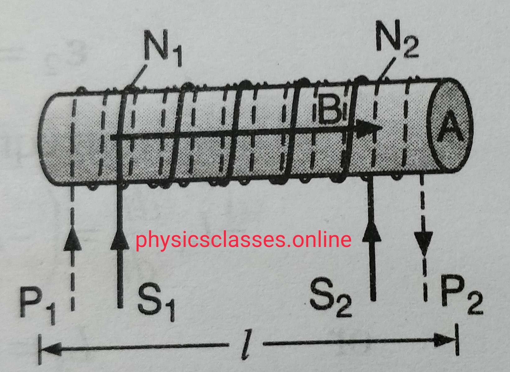
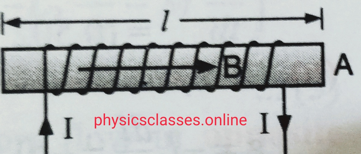
    Suppose a long air cored solenoid having ‘n’ number of turns per unit length . If current in the solenoid is ‘I’  the magnetic field within the solenoid B= µ0nI . If A is the area of cross-section of the solenoid , the effective flux linked with the solenoid of length ‘l’ ; ɸ=NBA……………………………….(i)

    where N is the total no. of turns of the solenoid . so ɸ= n l B A …………………………………….(ii) . substituting the value of B in this equation

    we get,

    ɸ =n l(µ0nI ) A  = µ0n2A l I .

    so , self-inductance  of solenoid L=ɸ/ I.=   µ0n2A l I / I  = µ0 n2 Al

    but n= N/l

    so self- inductance L= µ0 N2A/ l .

    If solenoid contains a core of ferromagnetic material , having relative permeability µr then self-inductance  L=   µ0µr N2A/ l .

    necessary picture of this topic  is shown above**.

  • SELF-INDUCTION

    SELF-INDUCTION

    Explain the term self-induction of a coil

    Self – Induction –

    It is the property of an electric circuit or coil by virtue of which it opposes any change of flux or current in it by inducing a current in itself is called self- induction. In another words we can say “self-induction is the inertia of electricity “. Due to self -induction an electric circuit resist any change of current through it .

    As we know magnetic flux linked with a coil is directly proportional to the current flowing through the circuit

    i.e.    ɸ α I ( ɸ= flux linked with the coil, and I is the current in the circuit )

    ɸ = LI ( L is the constant called coefficient of self- induction or self-inductance  or only inductance . )

    If current I =  1 ampere, then flux ɸ= L  . so we can define self-induction is the flux linked with the coil when unit current passes through the coil.

    as we know,

    emf  e= – dɸ/dt

    e= -d (LI)/ dt

    e= -L ( dI/dt)

    L= –  e/(dI/dt)

    So we can define self-inductance of a circuit is numerically equal to the induced emf setup in it when the rate of change of current through it is unity.

    Unit of self-inductance is Henry (H) .  We can define self-inductance of a coil is one Henry if 1 volt emf induced in the coil when rate of change of current through the coil is unity.

    To find the expression for self-inductance of long solenoid click here