In this topic we will discuss about ,what are the coherent sources of light? What are the necessary conditions to obtain coherent sources of light?why to independent sources of light can’t be coherent?
1. What are coherent sources of light?
Definition: Two sources of light are said to be coherent if they emit light waves of the same frequency (or wavelength) and maintain a constant phase difference with time.
Examples:
Two slits illuminated by the same monochromatic light source in Young’s double-slit experiment.
Two secondary sources derived from a single source of light.
2. Conditions to obtain coherent sources of light
The following conditions are necessary to obtain coherent sources:
1. Same frequency: Both sources must emit light waves of the same frequency or wavelength.
2. Constant phase difference: The phase difference between the two waves must remain constant with time.
3. Same state of polarization: For effective interference, the waves should have the same polarization.
4. Same source of origin: The sources should preferably be derived from a single source of light, because independent sources emit light with randomly changing phase differences.
5. Comparable amplitudes: For clearly visible interference fringes, the amplitudes of the two waves should be equal or nearly equal.
3. How are coherent sources produced?
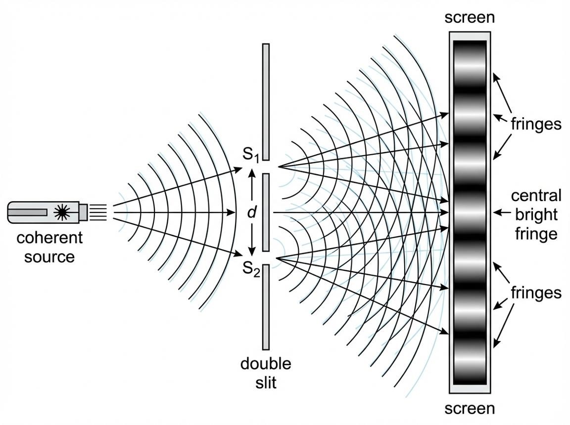
In Young’s double-slit experiment, monochromatic light from a single source first illuminates two narrow slits, \(S_1\) and \(S_2\). Since both slits receive light from the same source, they act as coherent sources and produce a stable interference pattern on the screen.
Important exam point: Two independent light sources cannot generally be coherent because their phase difference changes randomly with time.
4. Why can’t two independent light sources be coherent?
Two independent light sources cannot generally produce sustained, stable interference because:
They emit light independently.
The phase difference between their waves changes randomly with time.
Their emissions arise from independent atomic processes.
As a result, the interference pattern averages out over time.
Conclusion: To obtain a stable interference pattern, coherent sources are required. In Young’s double-slit experiment, both slits are illuminated by the same source, making them coherent.
Remember for exams: Coherent sources have the same frequency and a constant phase difference.
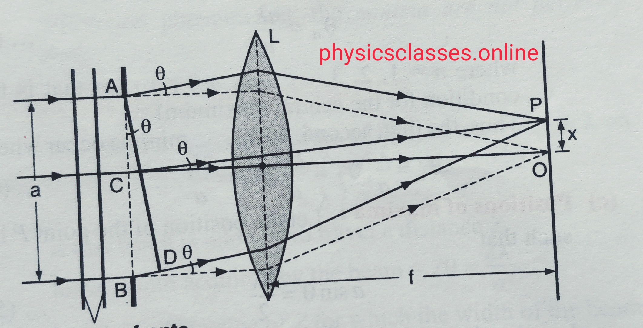
In this topic we will discuss what is diffraction of light , using single slit experiment formation of central max , position of secondary maxima and minima.
Diffraction of Light – Single Slit Experiment
diffraction single slit
1. What is diffraction of light?
Diffraction of light is the phenomenon of bending and spreading of light waves when they pass through a narrow slit or around the edge of an obstacle.
Diffraction is clearly observed when the size of the slit or obstacle is comparable to the wavelength of light.
In this topic we will explain the photoelectric effect and also will explain hertz’s observation and Hallwach’s and Lenard’s observation.
Photoelectric Effect: Hertz, Hallwachs and Lenard’s Observations
1. What is the Photoelectric Effect?
The photoelectric effect is the phenomenon in which electrons are emitted from the surface of a metal when electromagnetic radiation of a suitable frequency falls on it.
The emitted electrons are called photoelectrons, and the current produced by their motion is called photoelectric current.
Example: When ultraviolet light falls on a clean zinc plate, electrons may be emitted from its surface.
Important terms
Photoelectrons: Electrons emitted from a metal surface due to incident light.
Work function (ϕ): The minimum energy required to remove an electron from a metal surface.
Threshold frequency (): The minimum frequency of light required to produce photoelectric emission.
Stopping potential (): The minimum reverse potential required to stop even the fastest photoelectrons.
Einstein’s photoelectric equation is
where:
= Planck’s constant
= frequency of incident light
= work function of the metal
= maximum kinetic energy of emitted electrons
Since
This equation explains the main features of the photoelectric effect.
2. Hertz’s Observation (1887)
Heinrich Hertz
Heinrich Hertz was conducting experiments to demonstrate electromagnetic waves. During his experiments, he observed that ultraviolet radiation helped an electric spark pass between two metal electrodes.
Experimental observation
Hertz produced an electric spark between two metal electrodes.
He observed that ultraviolet light falling on the electrodes made the spark easier to produce.
When the ultraviolet radiation was blocked, the spark became more difficult to produce.
Conclusion
Hertz’s observation indicated that ultraviolet radiation could help release electrons from a metal surface, facilitating the discharge.
Importance: His observation was an early discovery of the photoelectric effect.
3. Hallwachs’s Observation (1888)
Wilhelm Hallwachs
Wilhelm Hallwachs studied the effect of ultraviolet light on electrically charged metal plates, especially a clean zinc plate.
Experiment
A clean zinc plate was connected to a negatively charged gold-leaf electroscope.
The electroscope’s gold leaf diverged because the plate and electroscope carried negative charge.
Ultraviolet light was allowed to fall on the zinc plate.
The gold leaf gradually collapsed, indicating that the electroscope was losing its negative charge.
Observation and conclusion
Negatively charged zinc plate: It loses negative charge when exposed to suitable ultraviolet light.
Positively charged zinc plate: It does not readily discharge through photoelectric emission because the emitted electrons are attracted back to the positively charged plate.
Uncharged zinc plate: It can become positively charged after photoelectrons escape.
Conclusion: Ultraviolet light causes electrons to leave the zinc surface.
This provided clear evidence that light can cause the emission of electrons from a metal.
4. Lenard’s Observation (1902)
Philipp Lenard
Philipp Lenard investigated photoelectric emission using a metal surface and an apparatus in which emitted electrons could be collected and measured.
Experimental setup
In a typical arrangement:
Light falls on a metal cathode.
Photoelectrons are emitted from the cathode.
A collector electrode (anode) collects the electrons.
The resulting photoelectric current is measured using an external circuit.
Main observations of Lenard
1. Photoelectric current depends on light intensity.
For light of frequency above the threshold frequency, increasing the intensity generally increases the number of emitted electrons per second. Therefore, the photoelectric current increases.
2. Maximum kinetic energy depends on frequency.
Increasing the frequency of incident light increases the maximum kinetic energy of photoelectrons, provided the frequency is above the threshold.
3. Existence of stopping potential.
A reverse potential can be applied to oppose the motion of photoelectrons. At a particular reverse potential, even the fastest electrons cannot reach the collector, and the current becomes zero.
Kmax=eVs
Here, e is the magnitude of the electron’s charge and Vs is the stopping potential.
4. Threshold frequency exists.
Below a certain minimum frequency, no photoelectrons are emitted, even if the intensity of light is increased.
Conclusion: Lenard’s experiments established important properties of photoelectric emission and showed that the energy of photoelectrons is related to the frequency of incident light.
5. Comparison of Hertz, Hallwachs and Lenard
Scientist
Main observation
Significance
Hertz (1887)
UV light made an electric spark easier to produce.
Early discovery of photoelectric emission.
Hallwachs (1888)
UV light discharged a negatively charged zinc plate.
Demonstrated that electrons leave the metal surface.
Lenard (1902)
Studied emitted electrons, their current, kinetic energy and stopping potential.
Established important experimental laws of the photoelectric effect.
6. Key results to remember for exams
Intensity of light
Increasing intensity increases photoelectric current, provided the frequency is above the threshold.
Frequency of light
Increasing frequency increases the maximum kinetic energy of photoelectrons.
Threshold frequency
Below the threshold frequency, photoelectric emission does not occur, regardless of intensity in the ordinary one-photon photoelectric effect.
Stopping potential
The stopping potential depends on the maximum kinetic energy, and therefore on the frequency of light for a given metal.
In this topic we will discuss what is optical fibre , what is its working and its important application.
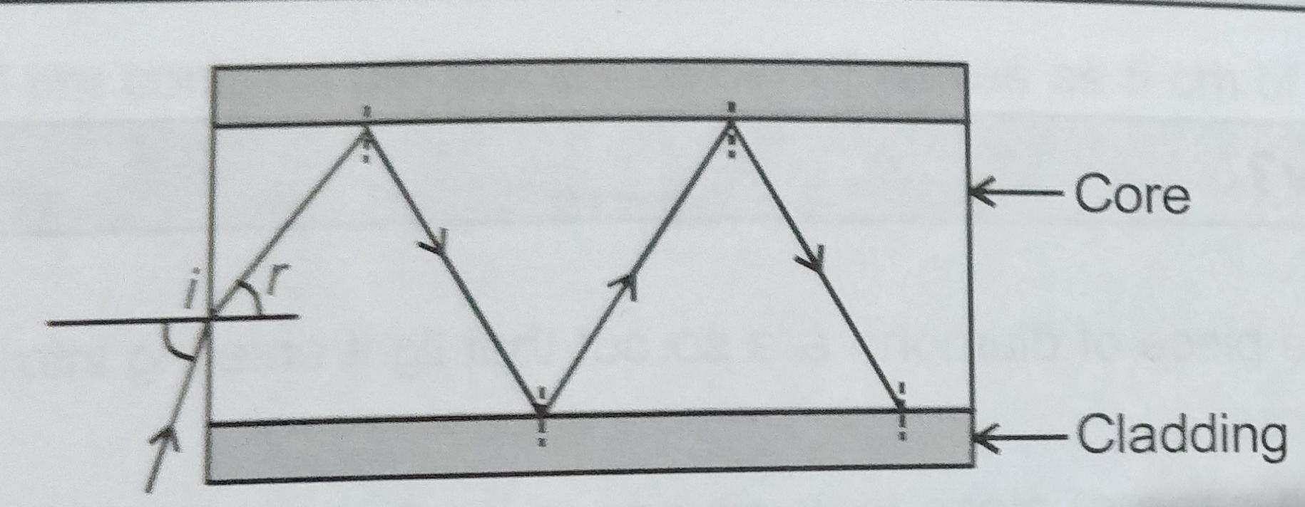
Optical fibres – It is a device based on Total internal reflection by which signal may be transmitted from one location to another. It is a thin fibre of plastic specially coated glass , in which light enters at one end leaves it at other end suffering a number of total internal reflection with little loss of energy . it works even it is bent or twisted.
The structure of The structure of optical fibre consists of a core surrounded by cladding . Core ( very high quality glass/silica/plastic) is denser medium of refractive index µ1 and cladding ( glass/plastic) is relatively rarer medium of refractive index µ2 such that µ1 > µ2 .When light incident at one end of the core gets reflected and will be incident on the interface between the core and cladding at an angle greater then the critical angle and light continues reflecting in the core. After several reflection light comes out to the other side i.e. at the destination.
Application of optical fibre –
( I ) It is used to transmit light without loss of intensity over a long distance of several kilometers .
(ii) It is used in the in the manufacture of medical instruments, called endoscope for visual examination of stomach and intestines etc. of patients.
(iii) It used for telecommunication, i.e., in transmitting audio and video signals to long distance.
(iv) It is used to measure the blood flow to the heart in the form of photometric sensor.
(v) It is used to measure refractive indices of the liquid.
Application of total internal reflection ( T.I.R) –
T.I.R in nature and its technological application-
Brilliance of diamond- The brilliance of diamond is due to the total internal reflection of light. Refractive index for diamond is very large which is near about 2.42 , so that critical angle for diamond air is 24.40. The diamond is cut suitably so that light entering the diamond from any face falls at an angle greater than 24.40. Therefore , it suffers multiple T.I R. at various faces , and remains within the diamond , falling to come out . Hence the diamond sparkles.
Mirage– Mirage is an optical illusion of water observed generally in desert in hot summer day. An inverted image of an object such as tree is observed along with the object as if the tree were on the bank of a pound of water.
Optical fibres – It is a device based on Total internal reflection by which signal may be transmitted from one location to another. It is a thin fibre of plastic specially coated glass , in which light enters at one end leaves it at other end suffering a number of total internal reflection with little loss of energy . it works even it is bent or twisted.
The structure of The structure of optical fibre consists of a core surrounded by cladding . Core ( very high quality glass/silica/plastic) is denser medium of refractive index µ1 and cladding ( glass/plastic) is relatively rarer medium of refractive index µ2 such that µ1 > µ2 .When light incident at one end of the core gets reflected and will be incident on the interface between the core and cladding at an angle greater then the critical angle and light continues reflecting in the core. After several reflection light comes out to the other side i.e. at the destination.
Application of optical fibre –
( I ) It is used to transmit light without loss of intensity over a long distance of several kilometers .
(ii) It is used in the in the manufacture of medical instruments, called endoscope for visual examination of stomach and intestines etc. of patients.
(iii) It used for telecommunication, i.e., in transmitting audio and video signals to long distance.
(iv) It is used to measure the blood flow to the heart in the form of photometric sensor.
(v) It is used to measure refractive indices of the liquid.
Totally reflected glass prism – Prism designed to bend light by 900, or 1800 the phenomenon of total internal reflection , such prisms are used to invert images without changing their sizes.
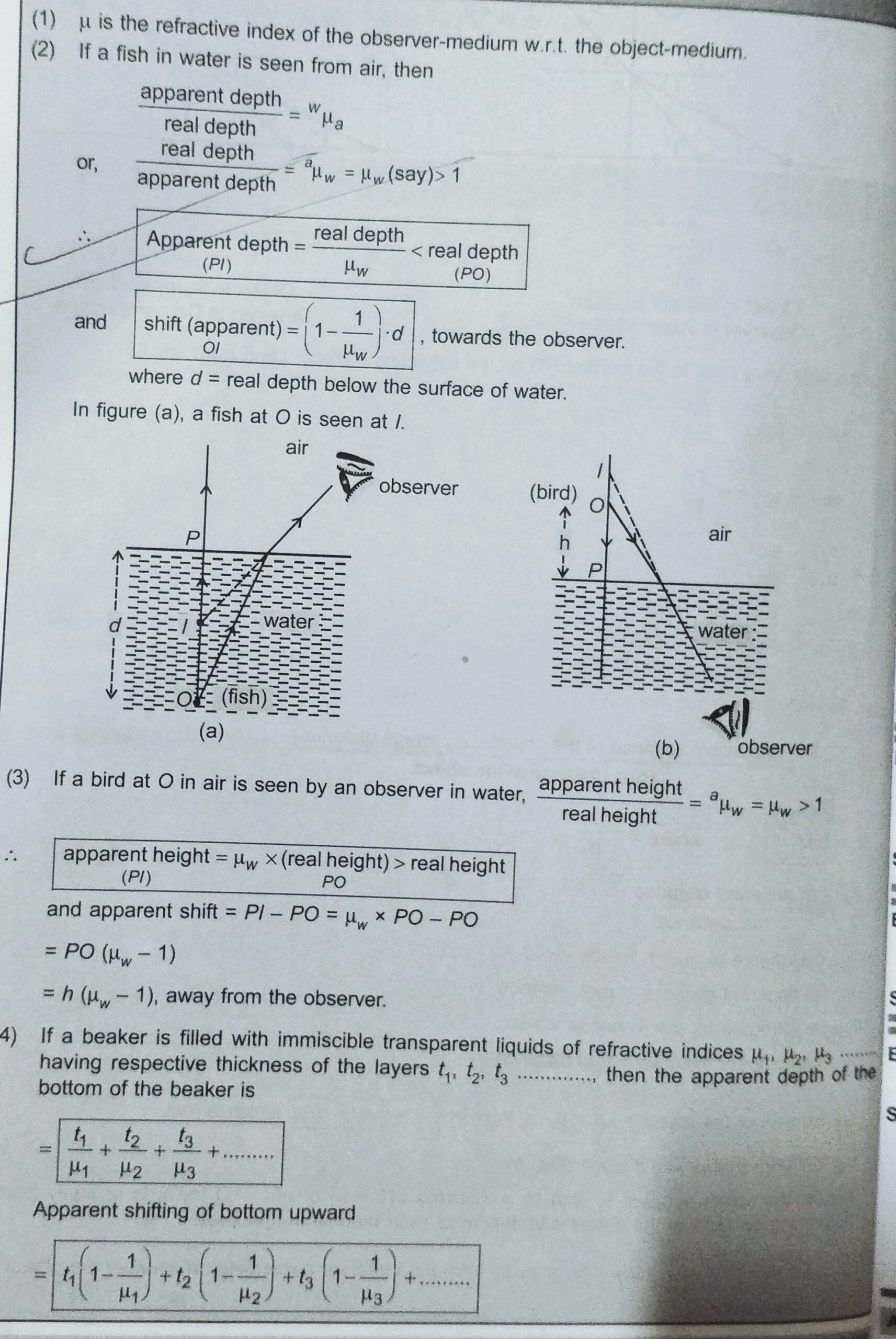
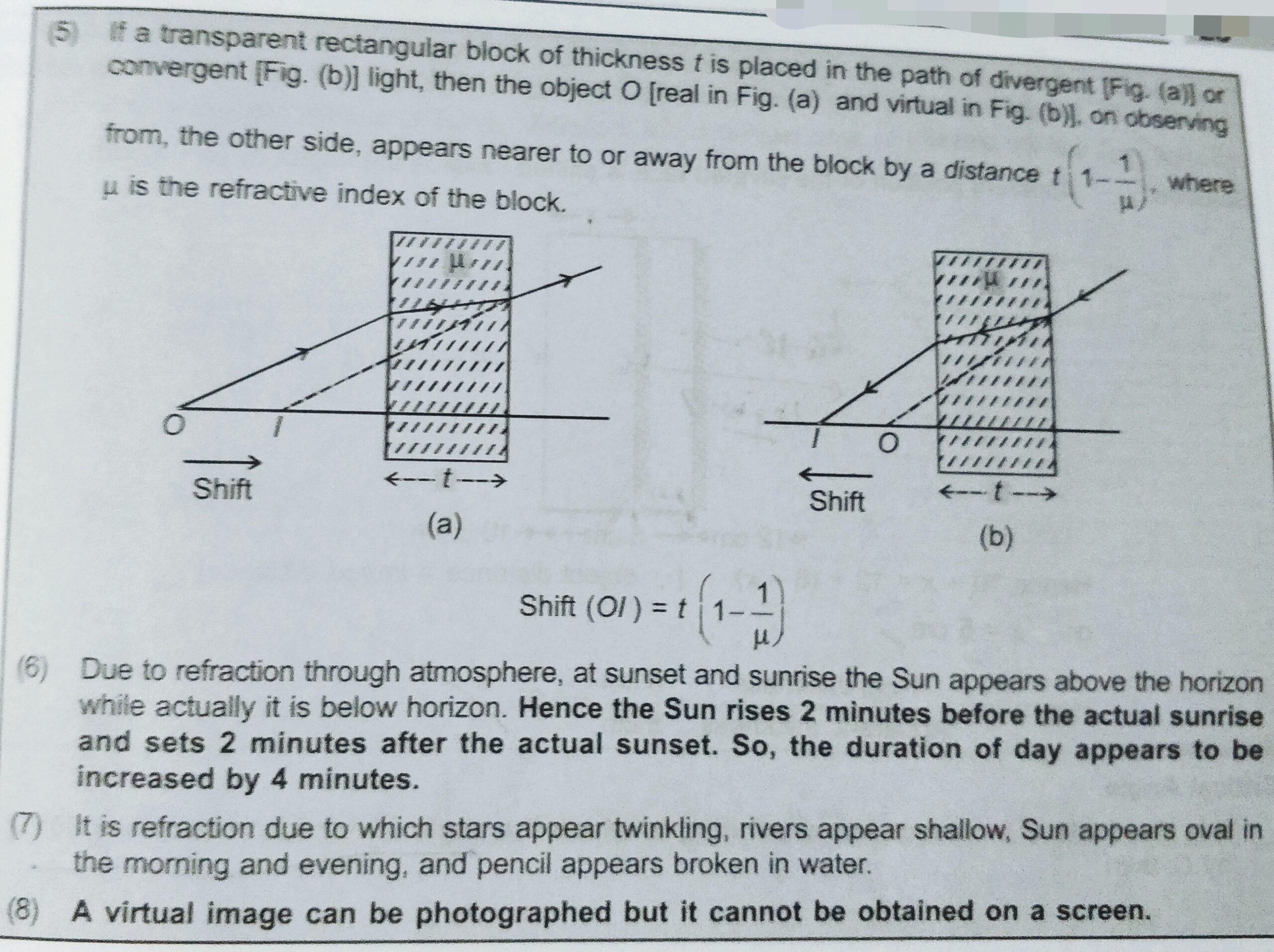
A water tank appears shallower i.e. less deep then what actually is. When we observe an object which is inside the water or any transparent liquid it appear higher then its actual position . This is because when light travels from denser to rarer it bended away from the normal . And we can understand the inverse of this process that when a fish observe an object which is placed above the water level then it appears higher then its actual height from the surface of water this is because when light travels from rarer to denser medium light banded towards the normal.
To watch the video of this topic click on the link given below-
The relation between real depth and apparent with the refractive index is given in point 2 and point 3 below.
In this note we will discuss about the very important points on the refraction of light , every students must keep it in the mind . It is use ful for objective point of view.
Keep in your mind-
Some important thing for refraction of light.
1. Refractive index µ=c/v where c is the velocity of light in air or vacuum and v is the velocity of light in given medium.
2. The speed of light in air slightly less than the speed of light in vacuum.
3. The medium having greater refractive index is called denser and the other is rarer.
4. While going from a denser medium to rarer medium , the refracted ray bends away from the normal and vice-versa.
5. Snell’s low states that µ = sin I /sin r { µ>1 if light moves from rarer to denser and µ<1 if light moves from denser to rarer.}.
6. As we know 1µ2= v1/v2 ,
Therefore , 1µ2 x 2µ1=[v1/v2 x v2/v1]=1
Or ,
1µ2=1/ 2µ1 .
Similarly, 1µ2 x 2µ3x 3µ4 x…………..=1.
7. Laws of refraction is valid for all types of surface separating for two media i.e. the separating may be plane or curved.
8. The angle of deviation on refraction is given as ‘ angle of deviation’ =|i-r|.
9. If incident ray is normal, refraction takes place without bending. In this case I = r = 00.
15. Optical path is the distance travelled by light in vacuum in the same time travel in which it has travelled a distance x in a medium of refractive index µ . i.e. optical path = ct =cx/v=µx.
16 According to Cauchy’s formula, refractive index µ= A+ B/(wavelength)2.
Having saw this result we can say that, as wavelength increases refractive index decreases and vice-versa.
To solve the objective questions of this chapter ray optics click here-
In this topic we will discuss about the magnetic elements of earth. All three kinds of magnetic elements of earth , angle of dip,angle of declination and horizontal components of earth magnetic field.
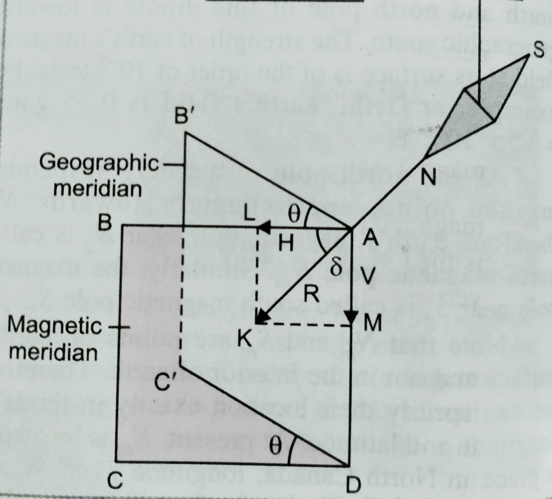
Magnetic elements of earth at a place are the quantities which describe completely the magnitude and direction of magnetic field at that place.
There are three magnetic elements of earth-
(i) Magnetic declination (ϴ);
(ii) Magnetic inclination or angle of dip (ẟ);
(iii) Horizontal components of earth’s magnetic field(H).
(i) Magnetic declination (ϴ);-
The small angle between magnetic and geographic axis at a place is known as magnetic declination at that place .
Or, In other words we can define , angle between geographic and magnetic meridian at a place on earth is known as the magnetic declination at that place.
(ii) Magnetic inclination or angle of dip –
Magnetic inclination at a place on the earth is the angle between total strength of magnetic field and horizontal lines in magnetic meridian.
The value of angle of dip at a place on the earth is measured using an instrument called ‘ Dip circle’.
(iii) Horizontal component-
It is the components of total field strength of earth’s magnetic field in the horizontal direction in magnetic meridian.
As shown in figure. , total field strength is represented by AK and angle <BAK = ẟ
Then the magnetic field along AB ( horizontal) is given as
H = R cos ẟ………..(i)
And magnetic field along AD is given as V= R sin ẟ ………….(ii)
Squiring and adding equation (i) and (ii) is given as
H2 + V2 = R2 ( Cos2ẟ+ Sin2ẟ) ;
So , R = √( H2 + V2) …………(III)
Again if we divide (ii) by (i) we get
R sinẟ/Rcosẟ = V/H
Or, Tan ẟ = V/H …………………(iv)
[**** important information about angle of dip –
(1). At a place on the magnetic poles , total earth’s magnetic field is perpendicular to the surface of earth .( ẟ=900 )
So, H = R cos 900 = 0
It means R = V ( total magnetic field is only in vertical direction)
(2) At a place on equator , total magnetic field is parallel to the earth ( ẟ=00)
So , V= Rsin00 = 0
It means R = H ( total magnetic field is in horizontal direction).
(3) In a vertical plane at an angle ϴ with the magnetic meridian.
Then apparent H’ = H cos ϴ
Again, apparent V’ = V,
Therefore tanẟ’ = V’/H’ = V/Hcosϴ = tanẟ/cosϴ ; (ẟ’ is the apparent value of angle of dip).
(4) If ẟ1 and ẟ2 are observed angle of dip in two arbitrary vertical planes which are perpendicular to each other then the true angle of dip ẟ is given as –
Cot2ẟ=cot2ẟ1 + cot2ẟ2.
(5) If λ is the magnetic latitude at a place, then it can be shown that the angle of dip at that place is given as , tanẟ = 2 tan λ …]
In this topic we will discuss about Magnetic field of earth. And also cause of earth’s magnetism, and magnetic and geographic axis and meridian.
Magnetic field of earth –
In 1600 Sir William Gilbert first suggested that earth behaves like a magnet , it is huge magnet itself. The following evidence explain it-
When a magnet suspended freely then it always comes in rest along the north south direction.
2.When we put a soft iron piece under the surface of earth in the north south direction, then it acquire the properties of magnet after some time .
When we draw the field lines of a magnet, we come across neutral points . At these points magnetic field of the earth neutralize magnetic field due to the magnet .
Cause of earth magnetism –
Some important postulates are given below , but exact cause is still unknown-
In 1600 William Gilbert suggested that the earth itself is a huge magnet.
2. According to Prof. Brackett , due to the rotation of earth , about its axis earth gets magnetic property , and starts behaving like a magnet. Every substance on the earth behave as a charge particle due to rotation of earth. It is a circulating currents develops due to charge particle , which are responsible for the magnetization .
As earth rotates , strong electric currents are setup due to movement of charged ions these current might be the cause of magnetization of earth.
4.Since earth core is very hot and molten which circulates the ions of Iron, Nickel in the highly conducting liquid region of the earth’s core might be forming current loops and producing earth’s magnetic field.
Important topic with Magnetic field of earth, is given below-
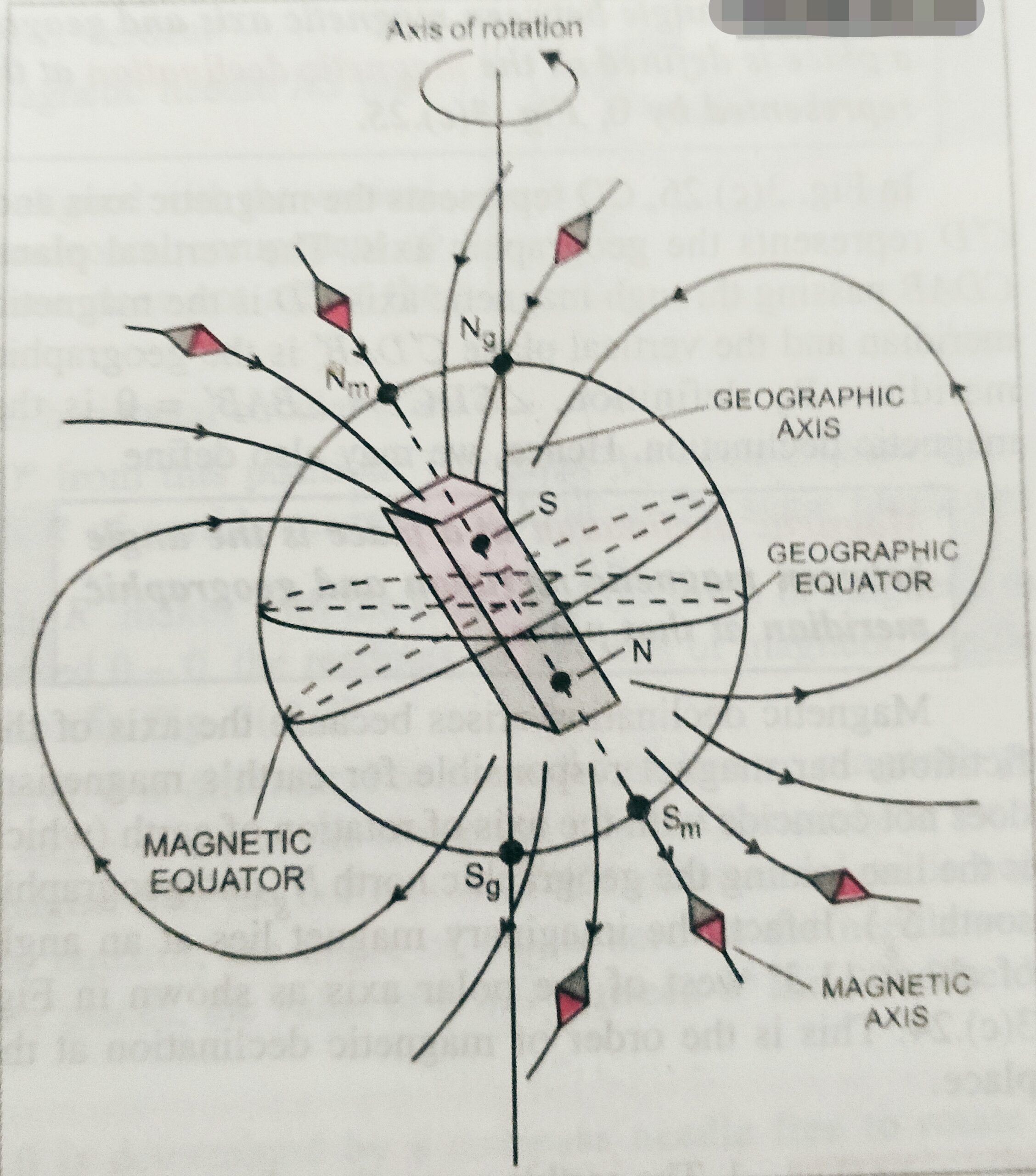
Straight line passes through the geographic north and south pole is called geographic axis. and the straight line passes through the magnetic north and south pole is called magnetic axis.
The very large circle on the earth perpendicular to the magnetic axis is called magnetic equator.
The vertical plane passing through the geographic north and south pole is called geographic meridian, and the vertical plane passing through the magnetic north and south pole is called magnetic meridian.
In this topic we will discuss about the ‘ Conversion of galvanometer into voltmeter ‘ . What is ammeter? and how can we convert a Galvanometer into voltmeter?
Before to read this topic ‘ Conversion of galvanometer into voltmeter ‘ students must know about the galvanometer and shunt .
This topic is very important topic for class 12th board examination and for other competitive examination ( for medical and engineering entrance examinations )
Voltmeter-
It is high resistance galvanometer used to measure potential difference between two points of a conductor or circuit.
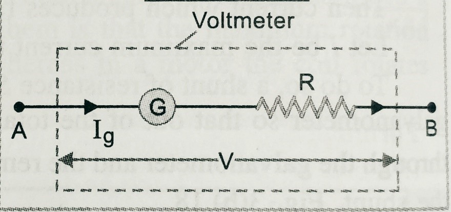
A galvanometer can be converted into voltmeter by connecting high value resistance in series with the galvanometer( as shown in figure).
IG is the current passes through the galvanometer,
R is the high value resistance in series with the galvanometer.
Let,
V is the potential difference of the galvanometer.
So we can write V = IG ( R + G)
Hence R =( V/IG)- G ;
Resistance of the voltmeter Rs = R + G ;
So we can say ,for ideal voltmeter the resistance of the voltmeter should be infinity.
This topic is very important for all state class 12th board examination and for other entrance examination , therefore it is important to solve the assignment of this topic .
In the assignment , we provide all kind of questions like , objective , short answer type, long answer type , numericals and hots . After solving the assignment of this chapter students will be able to improve there knowledge on this chapter.