Category: 12th Notes

  • Magnetic field at the center of a circular current carrying coil

    Magnetic field at the center of a circular current carrying coil

    Magnetic field at the center of a circular current carrying coil

    Before to know about this topic students must know Biot-Savart’s law.

    To get the notes on Biot-Savart’s law click here-

    Magnetic field at the center of a circular current carrying coil is the one of the application of Biot-Savart’s law . here we will derive the expression for Magnetic field at the center of a circular current carrying coil .

    syllabus class 12th physics (2020-2021)

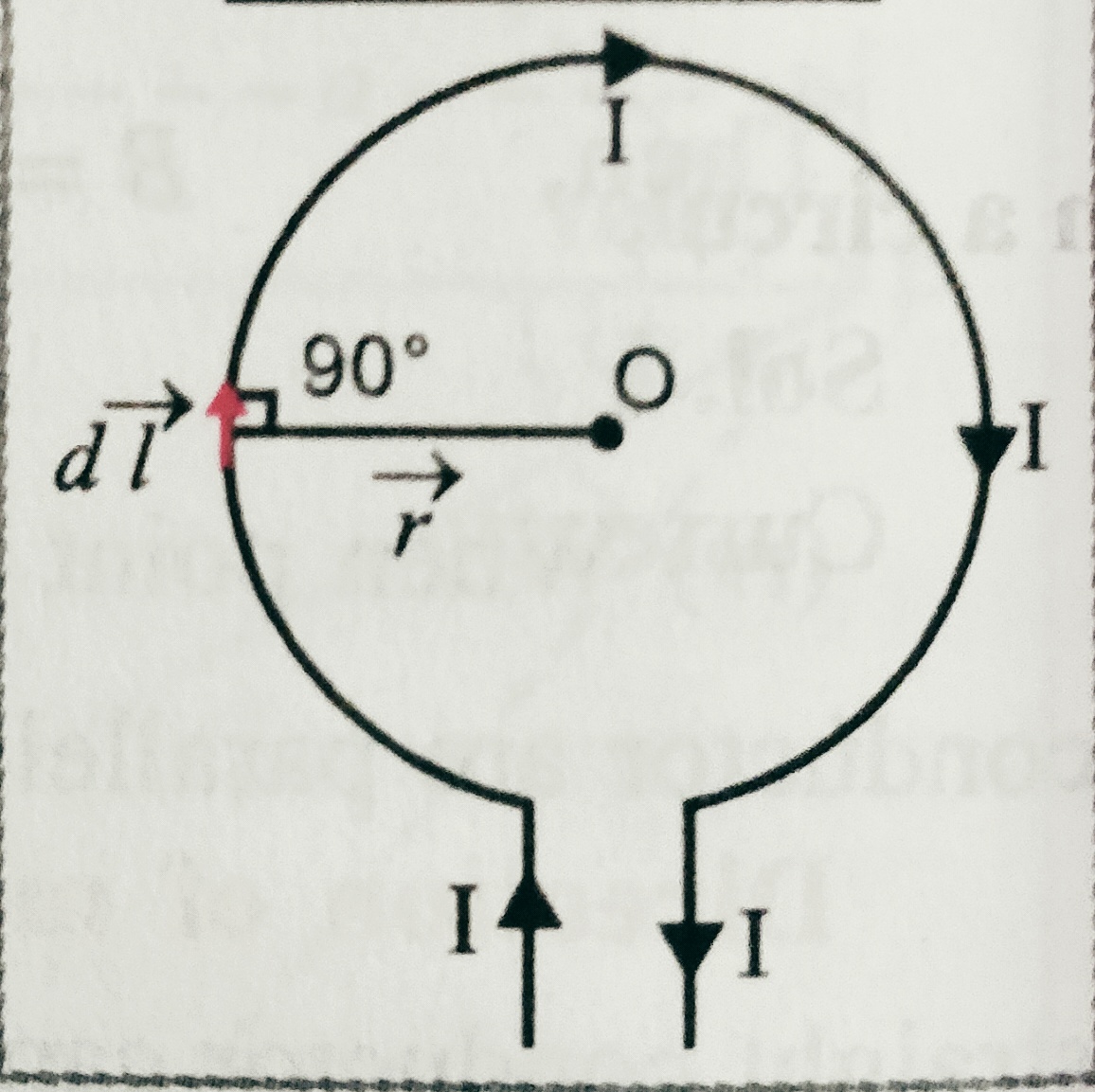
    Magnetic field at the center of a circular  current carrying coil – Consider a circular coil of radius ‘r’ having center ‘O’. suppose I be the current flowing through the coil , and we have to find the magnetic field at the center .

    Suppose a small element ‘dl’ which is the part of coil create a magnetic field dB at the center.

    According to Biot-savart’s law dB = (µ0/4Π) I dl sinθ/r2 . but ϴ=900,

    So we can write dB = (µ0/4Π) I dl sin900/r2 = dB = (µ0/4Π) I dl /r2 .

    Then magnetic field at the center due to complete coil

    B=∫ (µ0/4Π) I dl sinθ/r2 ( Taking limit 0 to 2∏)

    We get B= dB = (µ0/4Π) I 2∏r/r2  =  µ0 I /2r

    For an arc which is making angle ϴ at the center will be given as

    B= (µ0 I /4∏r)(Angle at the center )

    Or , B= (µ0 Iϴ /4∏r) ;

    The direction of magnetic field due to current carrying coil may be give by right hand rule , according to it if curled finger shows the direction of current then stretched thumb gives the direction of magnetic field .

    To watch the video of related topic click here-

    For next topic  magnetic field at a point on the axis of a circular current carrying coil . click here-

  • Force on a moving charge in a Magnetic field

    Force on a moving charge in a Magnetic field

    Force on a moving charge in a Magnetic field 

    In this topic Force on a moving charge in a Magnetic field , define the magnetic field and units and dimension of magnetic field .We will also know about Fleming’s left hand rule.

    Before to know about this topic Force on a moving charge in a Magnetic field we must learn about Oersted’s experiment and Ampere’s swimming rule. To know about this topic click here – 

    Force on a moving charge in a Magnetic field –

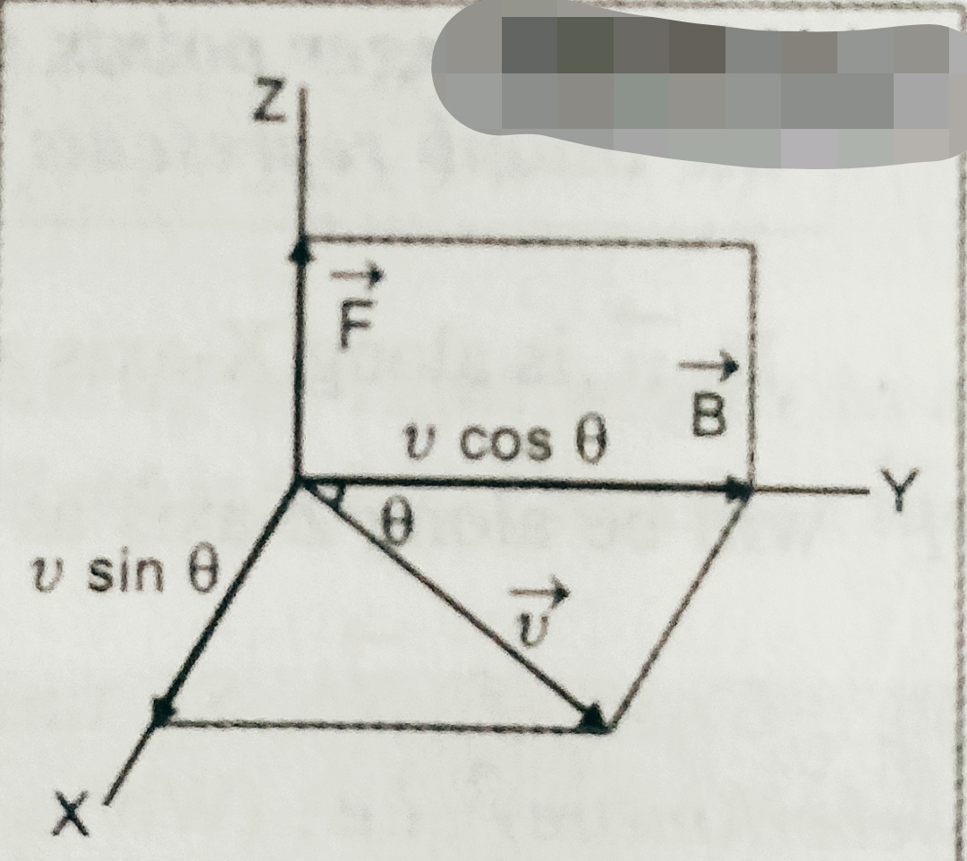
    Suppose a positive charge ‘q’ is moving with velocity ‘v’ at an angle ‘ϴ’ with magnetic field ‘B’. Then experimentally it is found that   force ‘F’ experienced depends on

    F α q ………(i)

    F α B……………….(ii)

    F α v sinϴ …………(iii)

    On combining these three equations we get ,

    F α q B v sinϴ

    Or, F =k q B v sinϴ ; where k is constant of proportionality k=1

    Then we can write F = q B v sinϴ or, F = q( x  )

    Here the direction of force is given by Fleming’s left hand rule or right hand screw rule .

    Fleming’s left hand rule –

     According to this rule when we stretch our left hand’s fore finger, middle finger and thumb such that they are perpendicular to each other , if fore finger shows the direction of field, middle finger shows the direction of current( +ve charge) then thumbs gives the direction of force .

     Definition of B (magnetic field intensity) –  

    As we have seen in the equation F = q B v sinϴ ;

    If  q= 1C , v=1m/s ϴ=900 i.e. sinϴ = 1 then   B= F ;

    So we can define magnetic field intensity at a point is equal to the force experienced by a unit charge moving with a unit velocity perpendicular to the direction of magnetic field at that point .

    Unit of  magnetic field ‘B’ –

    From the equation F = q B v sinϴ ,

    B = F/qv sinϴ ; then unit of B is NA-1m-1 = Tesla  (T) ,

    And dimension of B is [M A-1 T-2]


  • Magnetic effect of current,Oersted experiment and Amperes swimming rule

    Magnetic effect of current,Oersted experiment and Amperes swimming rule

    Magnetic effect of current, Oersted experiment and Amperes swimming rule –

    In this topic we will discuss about magnetic effect of current,Oersted experiment and Ampere’s swimming rule.

    Magnetic effect of current–

    When electric current passes through a conductor (conducting wire) then magnetic field developed around the conductor.

    The intimate relationship between electricity and magnetism was discovered 200 years ago , Oersted discovered in the year 1820 that a straight wire carrying current cause a deflection in a nearby magnetic compass needle.


    Oersted’s experiment and Ampere’s swimming rule-

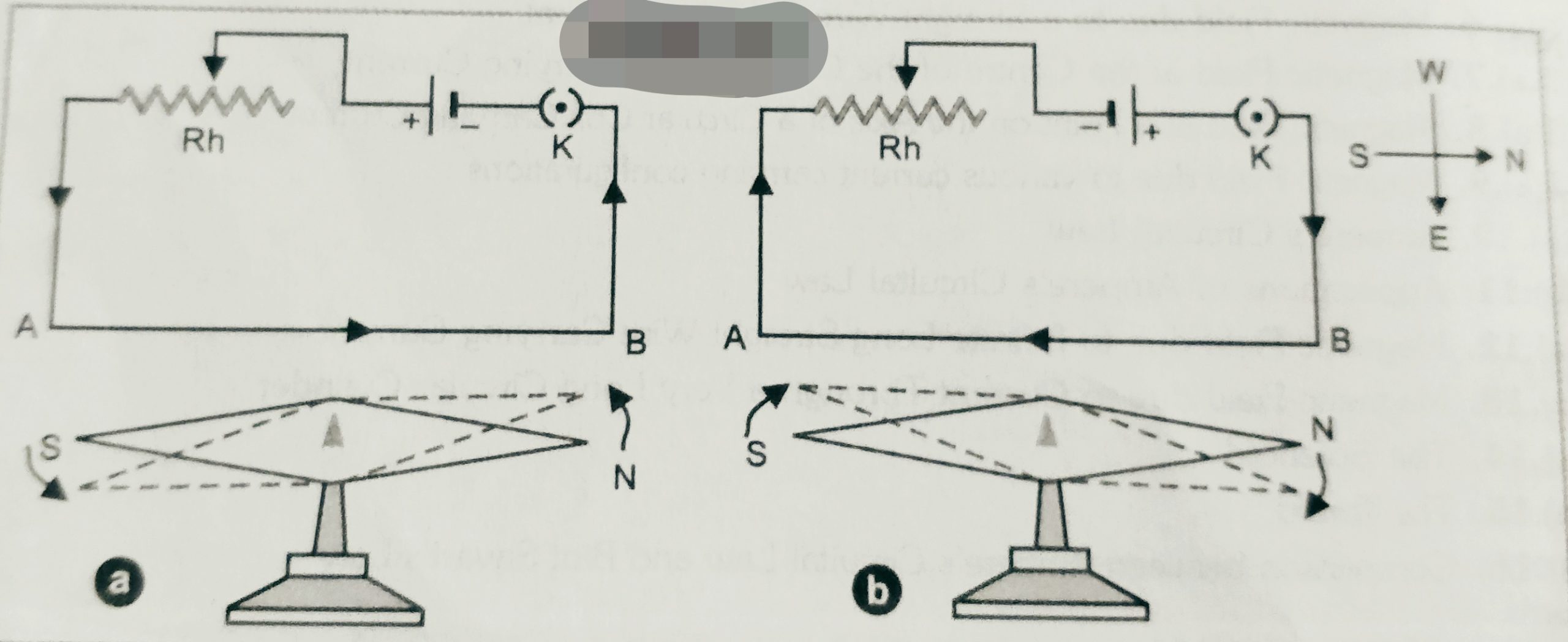
    According to Oersted’s experiment , we take a needle NS which is free to rotate . We place the needle above a current carrying wire AB . If current flows through the wire in the direction A to B   and from B to A then deflection in the needle shown in the figure . Since magnetic needle can deflect only in the interaction of the another magnetic field . so it is confirmed that due to flow of current in a conductor magnetic field setup across around the wire.

    The direction of deflection in the magnetic needle due to current in the wire is given by Ampere swimming rule . According to this rule ‘ If a man swimming along the wire in the direction of current with his face turned always towards the needle , so that the current  enters through his feet and leaves in his had , then north pole of the magnetic needle will be deflected towards his left hand’ .


  • Potentiometer

    Potentiometer

    Potentiometer

    In this topic we will discuss about Potentiometer,its working principle and its applications. Also we will know sensitivity of potentiometer.

    Before to know about this topic student must read the following topics –

    i.- Kirchhoff’s law,to read this topic click here-

    ii.- Wheatstone bridge,to read this topic click here-

    iii.-Mete bridge,to read this topic click here-

    Potentiometer – An instrument used to measure accurately the EMF or potential difference is called potentiometer.

    Principle– Its working based on the principle that the potential drop across a conductor is directly proportional to the length of the conductor , if constant current passes through the conductor having uniform area of cross-section .

    Construction –
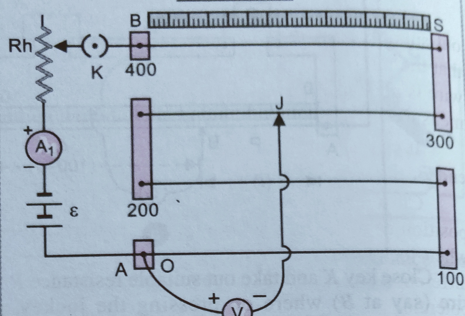
     As we know ,

    potential V=IR

    V = (ρl/A) I

    Since current is constant and area of cross-section is uniform  so V α l

    Or V = K l

    K = V/l ( K is a constant called potential gradient)

    [ calculation of potential gradient ( students don’t have to derive it in case of potentiometer it is useful to solve  the numerical questions) – if Rh = r and resistance of the wire is r and E is the emf of  driver cell  then ,  current through the circuit is , i = E/ (R+r)

    There fore potential difference at the end  the wire is v= i r

    V= {E/ (R+r) } r . so potential gradient  K = V/l = {E/ (R+r) } r/l. ]


    Application of potentiometer –

    1. Determination of potential difference using potentiometer –

    All the arrangements are shown in the figure-
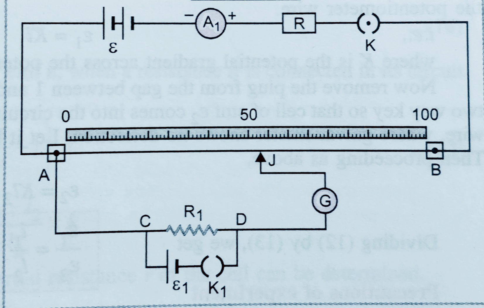
    Let key K is closed then current i starts flowing through the circuit , if  RAB is the resistance of the wire then , We can write current i = ε/R+RAB ;

    Now we close the key K1 also , in that case potential across the R1 is ‘V’ and null point J is at length ‘l’ as shown in figure .

    Then V = Kl ;

    But , K = VAB/ L   so we can write V =( VAB/ L)l   [L Is the total length of potentiometer wire]

    Here VAB = i RAB = (ε/R+RAB)RAB ;

    Therefore  V = [ {ε/(R+RAB)}l RAB]/L ;

    1. Comparison of emf of two cells –

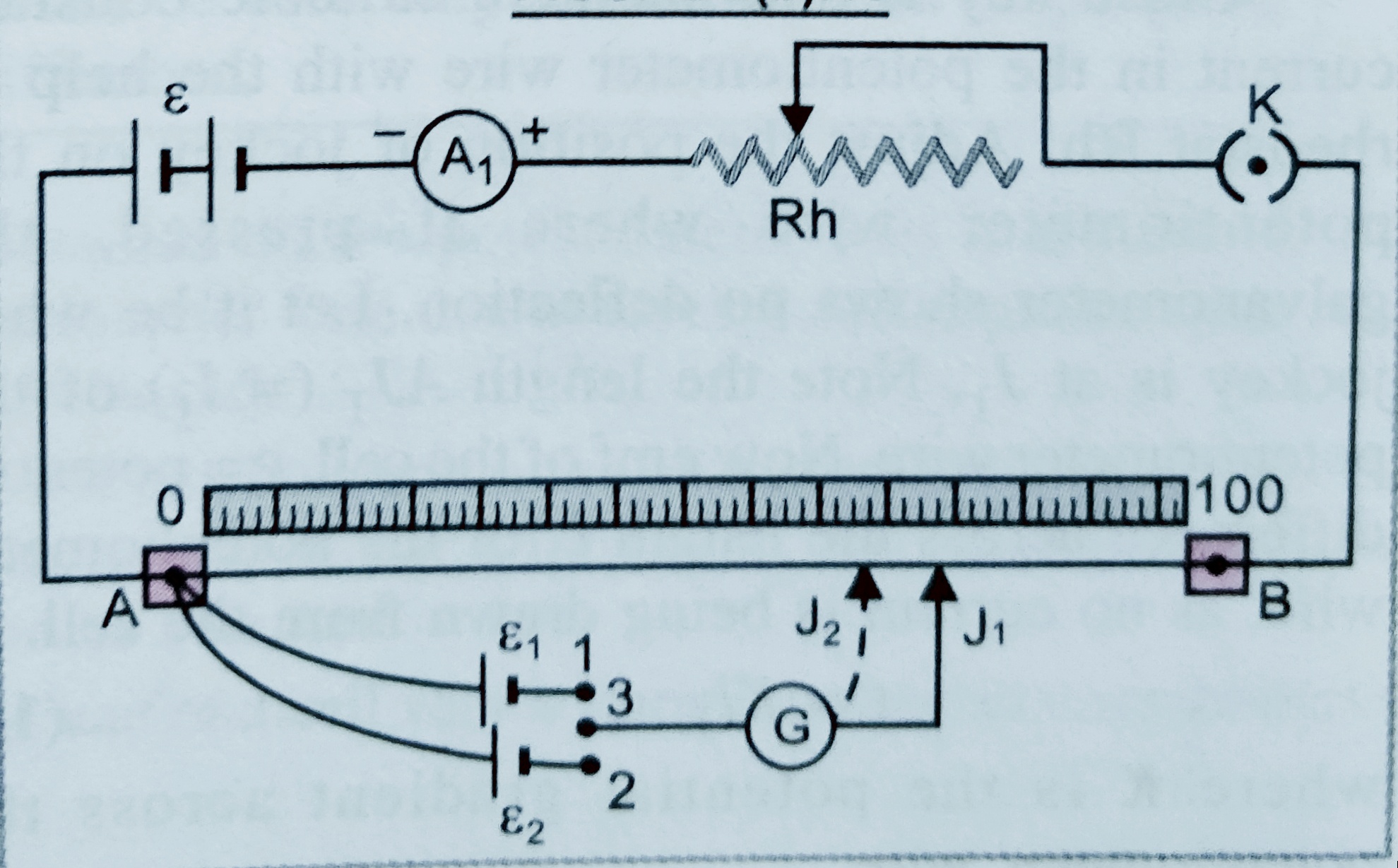
    A battery of emf ε is connected between the terminals A and B with variable resistance Rh , Now we have to compare the emf  ε1 and ε2 . We arrange the two cells having emf ε1 and ε2 as shown in figure . At first we connect the terminals 1 and 3 , let at that time J1 is the position where we grt null point , let length of A J1 is l1 so we can write  ε1= Kl1 ……….(i)

    Again 1 and 3 is de-attached and terminal 2 and 3 is connected  now this time we get null point at J2 , let AJ2­ = l2 . then we can write   ε2= Kl2 ………………….(ii)

    Dividing equation (i) by equation (ii) we get  ,  ε1/ ε2= l1/l2 …………..req. eq.

    Precautions of experiment-  (i) Current through the circuit must be constant .

    (ii) the emf of the driving cell (ε) must be greater than emf of the cells whose value has to be compared .

    1. Determination of the internal resistance of the cell –
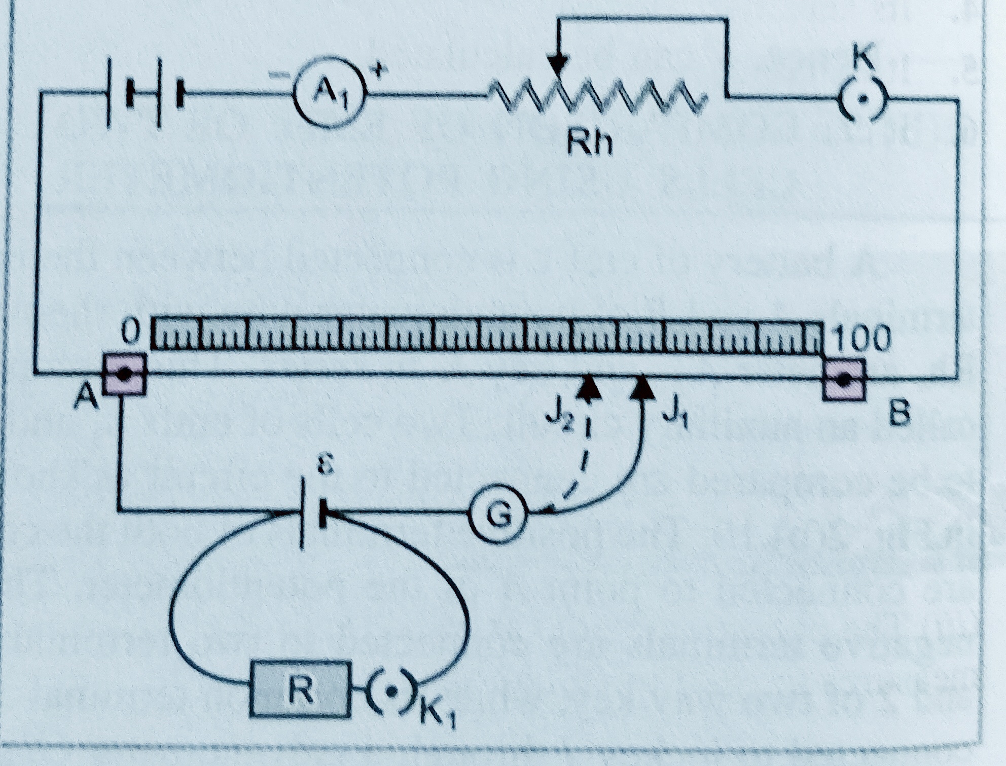
    To find the internal resistance r  of the cell  emf ‘ε’ we setup the circuit as shown in figure.

    Initially we close the switch ‘K’ and switch K2 is remain open .

    In that case null point is at J1 , let AJ1=l1

    Then we can write ε=Kl1………………(i)

    Now the switch K1 is closed then the potential across the resistance R is   ‘V’ . And in that case we get the null point at J2 . And AJ2=l2

    Then we can write V = Kl2   ………….(ii)

    Dividing (i) by (ii) we get  ε/V = l1/l2 ……………(iii)

    But we know that internal resistance of the cell   r = (ε-V /V)R = [ε/V-1]R ……….(iv)

    And from equation (iii) and (iv) we get , r = [l1/l2 -1]R ………Req. Eq.

    Sensitivity of potentiometer –

    The sensitiveness of the potentiometer means the smallest potential difference which can be measured with the help of potentiometer .

    The sensitiveness of the potentiometer can be increased ;

    (i)by increasing the length of the wire of the potentiometer ,

    (ii) by decreasing the value of potential gradient using reducing the current by increasing the resistance .

    Difference between EMF of a cell and potential difference –

    (i)  EMF -It is related with source of current

    P.D. – It is related with any two points of the closed circuit.

    (ii)  EMF – It cause of potential difference between two point of circuit .

    P.D. – It is an effect .

    (III)  EMF – It is the amount of work done in taking a unit charge once round the complete circuit .

    P.D. – It is the amount of work done to bring unit charge from one point to another point .

    (iv)  EMF – It is equal to sum of potential difference across all components of the circuit ( Including all          the cells connected  in the circuit .

    P.D. – In a closed circuit the different components of the circuit have different potential difference .

    (v)   EMF – It is independent of the external resistance and current drawn from the circuit .

    P.D. – It depends on the resistance between two points of circuit and current flowing through it .
  • Meter bridge or slide wire bridge

    Meter bridge or slide wire bridge

    Meter bridge or slide wire bridge

    In this topic we will discuss about Meter bridge or slide wire bridge . Principle of Meter bridge or slide wire bridge  ,  its working and, end errors with correction of end error.

    Before to know this topic students must read the following topics.

    i. Kirchhoff’s rule , To get the notes of this topic click here-

    ii. Wheatstone bridge , To get the notes of this topic click here-

    Meter bridge or slide wire bridge –

    It is a device used to find the value of unknown resistance . It works on the principle of wheat-stone bridge .

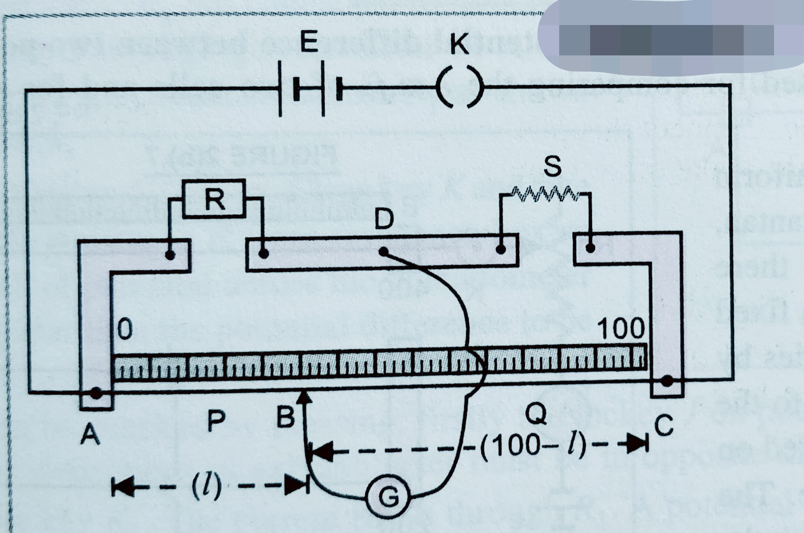
    It consist a wire of Constantan or Manganin of one meter length and having uniform area of cross-section . As shown in figure wire is stretched between AC , a cell with a key ‘K’ a resistance box R( known resistance ) is attached and an unknown resistance S  , in two gap as shown in figure .

    When switch ‘k’ is on , we start sliding the jockey from A to c , we notice there is a point where galvanometer shows no deflection ( known as null point) . Let this point is at B , let  AB = l

    so ,      BC = 100-l

    here RAB=ƍl/A ( Where A is the area of cross-section)

    RBC = ƍ(100-l)/A

    According to wheat-stone bridge principle (P/Q=R/S) We can write

    If meter bridge is balanced then R/RAB = S/RBC

    Or , R/ ( ƍl/A) = S / ƍ(100-l)/A

    Or, R/l =S/(100-l)    so    S = R(100-l)/l ……………eq.


    To see the video of meter bridge click on the link given below-


    Error end in the meter bridge- cause of the zero end error is following-

    (a) The resistance of the copper strip and connecting wire is not taken in account .

    (b)The zero mark of the scale may not start from the position where copper strip leaves the wire and 100 cm  mark may not on the position where the bridge wire just touches the copper strip .

    Processes to remove the end error –

    By changing the ‘R’ with ‘S’ and ‘S’ with ‘R’ and repeating the experiment . The average value of S determined earlier and now is free from end error .

    *** NOTES-  1. Null point ( where galvanometer shows no deflection) should be at the middle of the bridge wire . Because it becomes more sensitive when all four resistances are nearly same.

    2.The meter bridge can’t used to measure very high or very low resistance .

    1. the balanced point not effected after interchanging the position of galvanometer and battery .
  • Wheatstone bridge

    Wheatstone bridge

    Wheatstone bridge

    In this topic we will discuss about Wheatstone bridge ,its principle and balanced condition for Wheatstone bridge .And some important points for Wheatstone bridge.

    Before to know about Wheatstone bridge , students must read these topics first-

    i. Kirchhoff’s rule , to get the notes on this topic click here-

    ii. Ohm’s law, to get the notes on this topic click here-

    iii. Emf of the cells, To get the notes on this topic click here-

    Wheatstone bridge –

    It is an arrangement in which four resistances are arranged in the form of a bridge which is used for measuring one unknown resistance in terms of other three resistances .

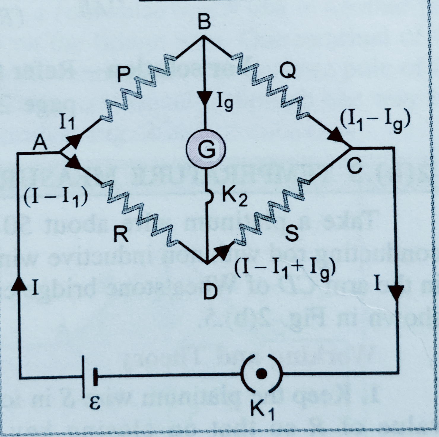
    Wheatstone bridge principle – It’s principle states that when four resistances P,Q,R and S are connected with a galvanometer and a cell in the form of bridge as shown in figure , the bridge is said to be balanced when there is no deflection shown by the galvanometer for this condition P/Q = R/S .

    As shown in figure , resistance P is in arm AB , Q is in arm BC , R is in arm AD and S is in arm DC . A cell of emf ‘ε’ and galvanometer is connected as shown in figure with  keys K1 and K2 . On closing key K1 and then key K2 if galvanometer shows no deflection then it is said that bridge is balance , and we will get  P/Q = R/S  .

    As shown in figure I is the current flowing through the cell , when it reaches to point A it divided in two parts I1 towards AB and ( I-I1 ) towards AD . Again when I1 reaches to B then current Ig flows through galvanometer and ( I1-Ig) towards C and current I-I1+Ig towards DC .

    Now applying Kirchhoff’s loop law in loop ABDA we get,

    I1P+IgG-(I-I1)R=0 …………………..(I)

    Again from loop BCDB we get   (I1-Ig)Q – ( I-I1+Ig)S-IgG=0………………(II)

    If galvanometer shows no deflection i.e. Ig=0 then eq (ii) may be written as

    I1P  =  (I-I1) R ………………….(III)

    And eq. (ii) may be written as ,

    I1Q  =  (I-I1) S ……………………..(IV)

    Dividing (iii) by (iv) we get P/Q =R/S  This proves wheat-stone bridge .

    Two view the video on Wheatstone bridge click here-


    *****Important point for wheat-stone bridge ***

    (1) Wheat-stone bridge is a null method , hence the measurement of unknown resistance is very accurate.

    (2) Wheat-stone bridge remain unaffected by the internal resistance of the cell and galvanometer.

    (3) it is not used to measure very high or very low resistances .

    (4) It becomes very sensitive when  resistance of all four arms are nearly same .


  • Kirchhoff’s rules

    Kirchhoff’s rules

    Kirchhoff’s rules

    In this topic we will discuss about , Kirchhoff’s rule and explanation of  its type.And also we will discuss, how Kirchhoff’s second rule loop rule/ potential rule , support the law of conservation of energy ?

    Kirchhoff’s rule 

    First rule ( junction rule /current rule ) –  According to this law when current flowing through several wires meet at a point ( junction) the at a junction in closed circuit is always zero .

    [ sign convention –  generally when current flows towards the junction is taken positive and when it moves away from the junction is taken negative . ]

    As shown in figure,  ‘o’ is the junction then according to Kirchhoff’s law  .

    -I1+I2-I3+I4+I5 = 0 …………………..Eq.

    Then from the above relation we can say at a junction current entering is equal to current leaving .

    Second rule ( loop rule / voltage rule ) – According to this rule for a closed loop the algebraic sum of change in potential must be zero . In another words we can say algebraic sum of potential differences across the cells and product of current and resistance across the resistor should be zero .

    [ ***sign convention-  select any point on the closed circuital loop you can move along your desired direction (clock or anti-clock wise direction) , when you reaches to the resistor then see the your moving direction and direction in which current flowing through the circuit the sign of ‘IR’( product of current and resistance ) if it is same the sign will be positive , if it is opposite then sign will be negative . And sign of potential or EMF of the cell will be positive if you touch positive terminal first , and sign will be negative if you touch negative terminal first ].

    To understand the loop rule see the following example –

    Suppose we have a loop shown in fig;-

    from the loop ABCDEFA,     -ε2+ ε1+i2R2 -i1R1=0

    or , ε1– ε2= i1R1– i2R2 ……………………..(i)

    again from the loop BEDCB ,  ε2-i3R3-i2R2=0

    or,  ε2= i3R3+i2R2………………………..(ii)

    and from the loop ABEFA, ε1 -i3R3-i1R1=0

    or, ε1 =i3R3+i1R1………………………….(iii)

    using equations (i),(ii),and (iii) we can find the all unknown quantities.

    *** Kirchhoff’s second rule loop rule/ potential rule , support the law of conservation of energy –

    In a closed loop the charges calculated around a closed loop in a particular direction due to electrostatic force which is conservative in nature . The work done by the electrostatic force on the circulating charge in a closed loop is zero . Due to it , the net charge in the energy of charge when goes on a closed loop is zero. It means there is no gain in energy  by circulating charges around a closed loop in a particular direction which is law of conservation of energy . Thus Kirchhoff’s supports the law of conservation of energy . ***

  • Grouping of cells

    Grouping of cells

    Grouping of cells

    In this topic we will discuss about grouping of cells in series and parallel. Also we will discuss about the mixed grouping of cells .

    Before to know about this topic student must know about emf of cells, internal resistance also the relation between emf / terminal potential and internal resistances , and the grouping of resistances .

    To know about emf of cells click here-

    To know about the relation between emf / terminal potential and internal resistances , click here-

    To know about grouping of cells click here-

    Combination of cells – 

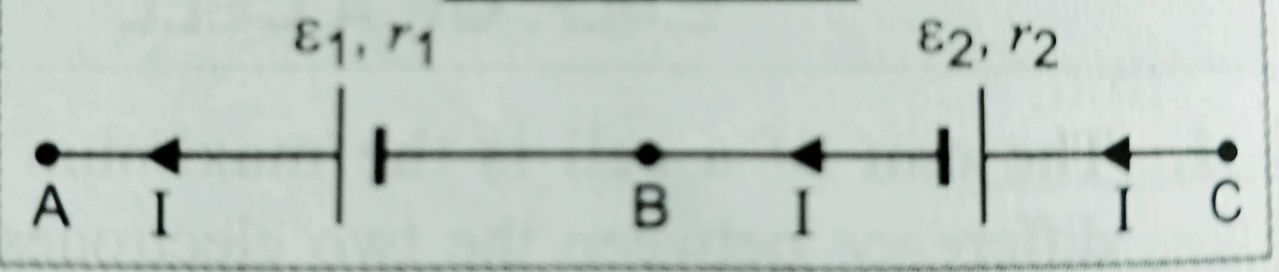
    (1) When two cells are connected in series  –  When negative terminal of first cell is connected to positive terminal of second then it is said that cells are connected in series . let the EMF of the cells and their internal resistances are [ ε1 , r1- ] and [ε2, r2 ] , are connected with external resistance R .

    Let VAB and VBC are the potential differences across AB and BC respectively . since the combination is series then current will be same (let I )

    Then VAB = ε1 – Ir1 ……………..(I)

    And VBC =  ε2 -Ir2  …………………(ii)

    Then VAC = VAB – VBC = (ε1 – Ir1 )– (ε2 -Ir2  ) = ε1+ ε2 – I(r1 + r2 )  …………(iii)

    Let εeq is the equivalent resistance of the combination req is the equivalent internal resistance of the combination .

    Then we can write , VAC =  εeq – Ireq ……………(iv)

    On comparing eq. (iii) and (iv) we get ,

    εeq= ε1+ ε2  and req = r1 +r2

    ** I f there are n cells connected in series then we can say

    ,    εeq = ε1+ ε2 + ε3+ ε4………… εn      and  , req = r1 +r2 + r3 +r4……….. rn    ;

    [ ***special cases –

    Case 1 –  If the direction of the combination of  cells are reversed then

    , εeq = ε1– ε2 and   req = r1 +r2

    Case 2 – If n identical resistances are connected in series then

    εeq = n ε   and  , req = nr and hence,  current through the circuit  I = n ε   /( nr+R)     ].


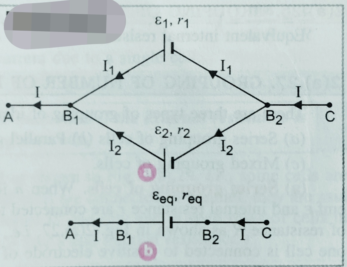
    (2) When two cells are connected in parallel –  If positive terminals of the cells are connected at one point and all negative terminal at another point then such kind of combination of cells are said to be in parallel combination .

    Let the EMF of the cells and their internal resistances are [ ε1 , r1- ] and [ε2, r2 ] , are connected with external resistance R .

    Let I1  and I2 are the current flowing  from both the cells as shown in figure , V is the terminal potential . then I 1 =( ε1-V)/r1   I2 = (ε2-V)/r2

    Net current I =  I1 + I2  ;

    I =  (ε1-V)/r1  +  (ε2-V)/r2…………………..(i)

    If  εeq is the equivalent resistance of the combination req is the equivalent internal resistance of the combination .

    Then I = (εeq-V)/req ………………….(ii) ,

    From equation (i) and (ii)

    (εeq-V)/req = (ε1-V)/r1  +  (ε2-V)/r2 ;

    (εeq-V)/req =  [ ε1/r1  +  ε2/r2] -V [1/r1 + 1/r2 ]

    (εeq-V)/req  = (ε1r2  +  ε2r1)/r1r2   – V [1/r1 + 1/r2 ]

    Then V = (ε1r2  +  ε2r1)/r1+r2 – I r1r2/r1+r2 ………………………(iii)

    But we know V = VAB = εeq – Ireq ………………(iv)

    On comparing (iii) and (iv) we get ,

    εeq = (ε1r2  +  ε2r1)/r1+r2

    and , req = r1r2/r1+r2 or [ 1/req= 1/r1 +1/r2 ].

    [***If there are n cells connected in parallel then ;εeq /req  = ε1 /r1  + ε2 /r2  + ε3 /r3  +………….εn /rn  and,   1/req = 1/r1 + 1/r2+1/r3………1/rn].

    [****Special case –

    If n identical cells are connected in parallel then  εeq =  ε

    Then current in the circuit will be given as  I =  ε /R+ r/n  =    n ε /nR+r ;     ]


    (3) Mixed grouping of cells – L et n identical cells are connected in series and m such series combination in parallel as shown in figure .


    As shown in each row there are n cells in series then total emf and resistance of each row will be ‘nε’ and ‘nr’ respectively   . Since there are ‘m’ rows in parallel then equivalent resistance will be given as

    1/rp =  1/nr+1/nr+1/nr………….to m terms ;

    So, rp = nr/m ,

    Therefore total resistance of the circuit will be ;- R+( nr/m) ;

    Current through the circuit flows will be –  I = nε / R+( nr/m) = mnε/MR+nr ; current

    [ ** special case – Through the circuit will be maximum when internal resistance is equal to external resistance   i.e. mR = nr ;or , R = nr/m   ].

  • Relation between electromotive force,internal resistance and terminal potential.

    Relation between electromotive force,internal resistance and terminal potential.

    Relation between electromotive force,internal resistance and terminal potential.

    In this topic we will discuss about electromotive force,internal resistance and terminal potential,relation between them . Also we will plot the graph between them .

    EMF , Internal resistance and terminal potential difference of a cell –

    EMF of a cell –  As we know electric current flows through a complete closed circuit ,when there is an source of external force which can bring the ions from low potential to high potential . This external for which makes the current carriers to move in a definite direction called electromotive force (EMF) . In another words we can define ‘ It is the maximum potential difference between two electrodes of the cell when no current flows through the circuits i.e. in open (off) circuit‘ .

    Unit of the EMF is Volt (V) and it is generally represented by ‘ε’.

    Internal resistance –

     It is the resistance offered by the electrodes and electrolytes of a cell to the passes of electric current through it. It is denoted by ‘r’ .

    its value is generally very low its value increases when cell becomes older and older .

    The value of internal resistance depends on (a)area of the electrodes immersed in the electrolytes ,(ii)nature of electrodes , (iii) distance between the electrodes and (iv)nature of electrolytes .

    Terminal potential difference –  Terminal potential difference of a cell is defined as the potential difference between the two electrodes of a cell in a closed circuit . it is denoted by ‘V’ . or simply we can define when current flows through a circuit then the potential difference across the end of the resistor. In a closed circuit the terminal potential difference of a cell is always less than the EMF of the cell .

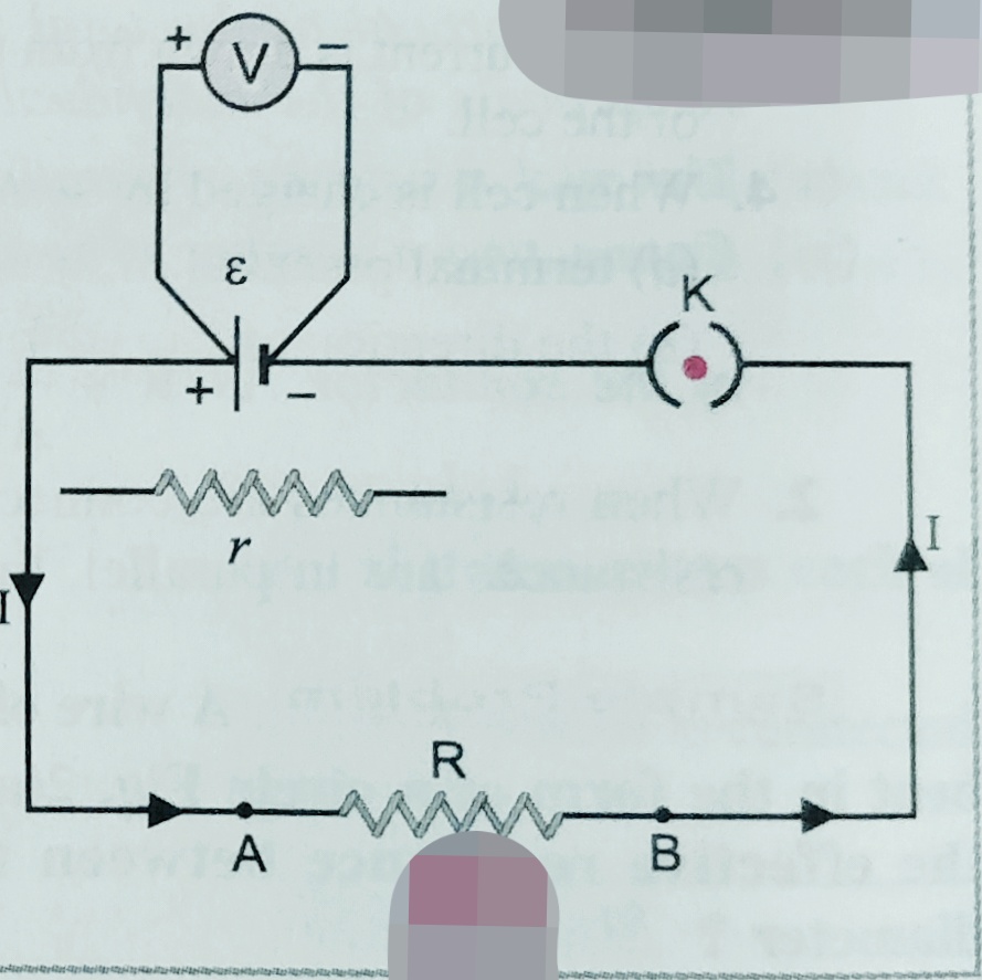
    Suppose , ε is the EMF of the cell , r is its internal resistance  which is connected with an external resistance R with the help of a key ( K ) as shown in the figure ,

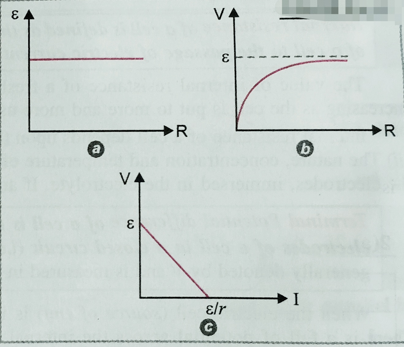
    If the key is not closed , the circuit remain open no current flows through the circuit , the  reading of the voltmeter is equal to emf ε . [ i.e. terminal potential of the cell is equal to the emf of the cell( V= ε) ] .

    When key is closed then current start flowing through the circuit,

    in that case emf of the cell   ε= I(R+r) = IR +Ir = V +Ir

    so we can write , V = ε -Ir ………………..eq.

    from the above equation  we just come to know ;

    case (1)- if circuit is open ( off) I=0   so, V = ε

    case (2) – If circuit is closed (on) , then  V < ε

    case (3) –  ** During the charging V > ε ;


    From the above equation  V = ε -Ir

    We can find  internal resistance  r = (ε -V)/I

    But I=v/R  so we can write   r = ( ε-V/V) R ……eq. to find the internal resistance of the cell .

    Graph between (a) ε and R (b) V and R (c) V and I; are  given below –