Category: 12th Notes

  • USES OF POTENTIOMETER

    USES OF POTENTIOMETER

    USES OF POTENTIOMETER

    Uses of potentiometer –

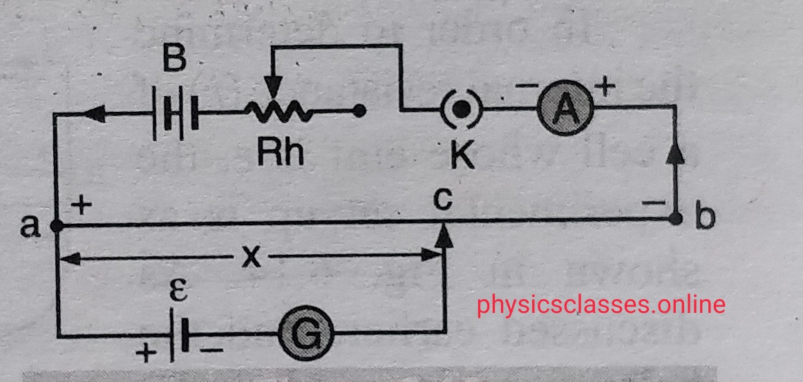
    • Measurement of emf of cell-


    POTENTIOMETER USE-1
    POTENTIOMETER USE-1

    Let ,

    E is the  emf of  driver cell  and ,  E1  is the emf of cell to be measured

    Here potential gradient K= [ {E / (R+r)} r]/l .

    Let l1  is the length of the wire from zero end where galvanometer shows no deflection

    Then E1 = K l1

    E1 =   [ {E / (R+r)} r]/l X l1

    • Comparison of EMFs of two cells


    • POTENTIOMETER USE-1
      POTENTIOMETER USE-2

      To find the emf of two cells we connect the two cells with the potentiometer  as shown in figure  having emfs E1  and E2  .

      When 1 and 2 is connected together let null point is at length l1  from zero end,

      Then E1 = K l1 …….(i)

      Again when 2 and 3 are connected , null point  is at length  l2 from zero end ,

      Then  E2 = Kl2 ……..(ii)

      By dividing (i) and (ii) we get E1 /E2 = l1 / l2 ………..(req. equation)

      To find the internal resistance of a cell –
      POTENTIOMETER USE-3
      POTENTIOMETER USE-3


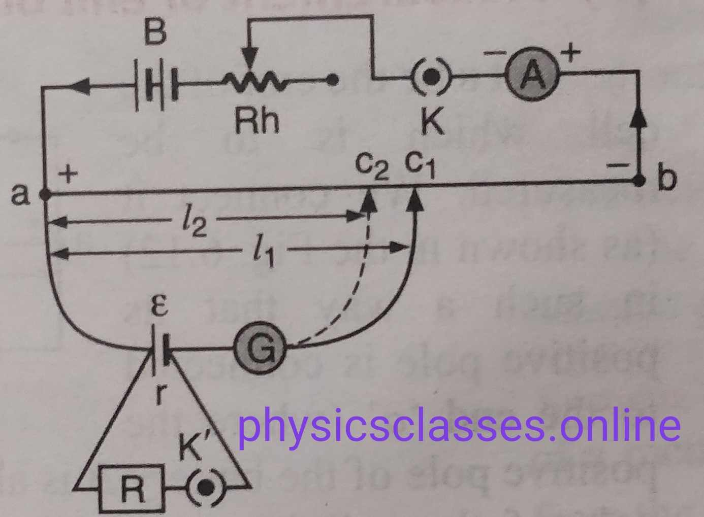
    Let,

    E – is the emf of the cell of which we have to find the internal resistance

    R – is the external resistance connected with  the cell

    R –  internal resistance of the cell

    Let initially  switch K’ is off and l1 is the length of the null point from the zero end .

    then E = K l1 ……….(i)

    After that switch K’ is switched on then the null point is at l2  from zero end

    then ( potential across R )       V = K l2 ……… (ii)

    E/V = l1 /l2 …………..(iii)

    But,  internal resistance r = [(E/V)-1] x R ……………..(iv)

    So, from equation (iii) and (iv)

    r =  [(l1 / l2 )-1] x R …….(req. equation)
  • POTENTIOMETER

    POTENTIOMETER

    POTENTIOMETER

    THIS TOPIC EXPLAIN ABOUT THE POTENTIOMETER

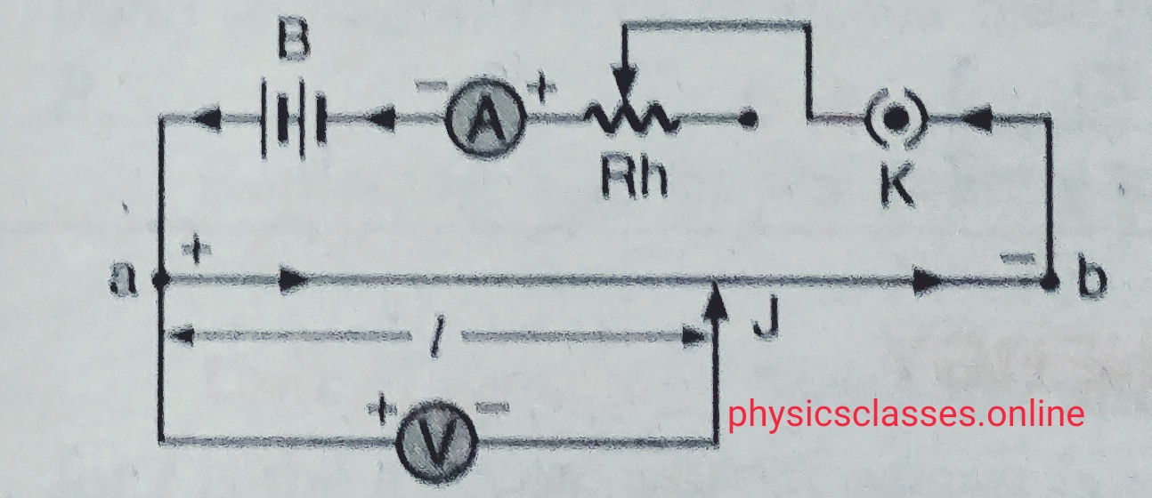
     Potentiometer – An instrument used to measure accurately the EMF or potential difference is called potentiometer.

    Principle– Its working based on the principle that the potential drop across a conductor is directly proportional to the length of the conductor , if constant current passes through the conductor having uniform area of cross-section .

    Construction –

    POTENTIOMETER
    POTENTIOMETER


    As we know ,

    potential V=IR

    V = (ρl/A) I

    Since current is constant and area of cross-section is uniform  so V α l

    Or V = K l

    K = V/l ( K is a constant called potential gradient)

    [ calculation of potential gradient ( students don’t have to derive it in case of potentiometer it is useful for the numerical questions) – if Rh = r and resistance of the wire is r and E is the emf of  driver cell  then ,  current through the circuit is , i = E/ (R+r)

    There fore potential difference at the end  the wire is v= i r

    V= {E/ (R+r) } r . so potential gradient  K = V/l = {E/ (R+r) } r/l. ]

    Potantiometer is preferred over the galvenometer to measure  potential difference across a conductor

  • MOVING COIL GALVANOMETER

    MOVING COIL GALVANOMETER

    In moving coil galvanometer we will learn about the working theory of a galvanometer and its conversion from galvanometer to ammeter and voltmeter

    To read the complete topic click here- Moving Coil Galvanometer

  • CYCLOTRON

    CYCLOTRON

    CYCLOTRON

    In this topic we will, discuss about working of cyclotron , its principle, construction and its limitations.  (** this topic is removed from the syllabus of class 12th, board examination).To know the complete syllabus click on the given link-

    Before to know about the cyclotron students must know  Force Acting on a Charge Particle Moving in a Uniform Magnetic Field; To get the notes on this topic click here-

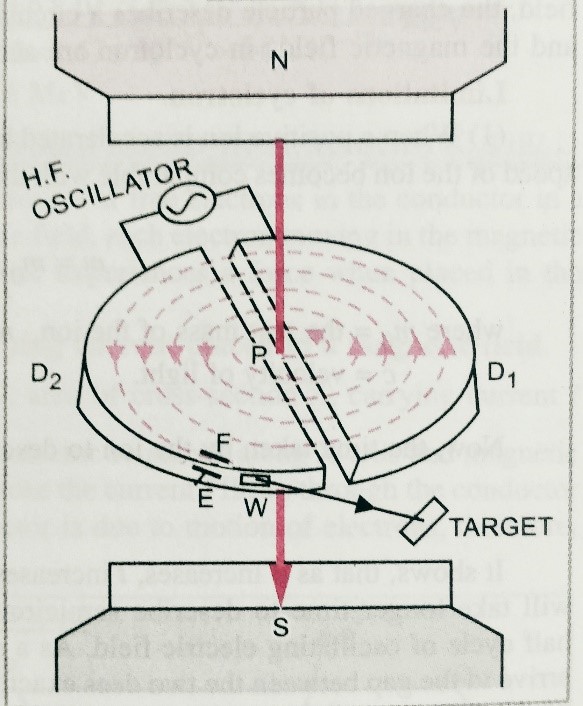
    Cyclotron-

    It is a device used to accelerate positive charged particles like proton, deutron , alpha particles etc . with desired velocity.

    Principle– Its working based on the principle that a positive charge particle can be accelerated to a sufficient high energy with the help of oscillating electric field with the help of perpendicular strong magnetic field .

    Construction– It consist two D-shaped chamber ( Dees)  D1 and D2 , which are placed slightly separated with each other between two poles of the magnet N- pole and S–pole ( as shown in figure. ) Dees are connected with an high frequency oscillator ( cause of variable electric field).

    Working and theory –  suppose initially the D1 is negative and D2 is positively charged , then the positive charged particle at point P starts to move towards D1 , but due to perpendicular magnetic field it starts moving on a circular path. If r is the radius of the circular path then ,

    mv2/r  = qvB

    So r = mv/qB ;

    Time taken by the charged particle to complete half cycle  t= ∏r/v = ∏m/qB ;

    When particle reaches to D1 at the same time D1 becomes positively charge and D2 negatively then again charge particle starts to move towards D2 with the circular path with greater radius . similarly charge particle remain describing the circular path with greater radius and greater speed and at an instant it ejected through the window with high kinetic energy .

    Maximum energy of charged particle–  suppose v0 , r0 is the  is the maximum velocity and maximum  radius of the circular path followed by the charged particle ,

    Then ,m v0 2/ r0 = B q v0  or ,  v0 = Bq r0/m ,

    Therefore maximum kinetic energy  k = ½ mv02 = B2 q2 r02 / 2m ;

    Cyclotron frequency –

    Angular velocity  ω=  Bqr/mr = Bq/m ……………..(3)

    here frequency  f=ω/2∏ = Bq/2∏m  ( here frequency is independent of velocity)………….(4)

    limitations of cyclotron-

    1. When a positive ion is accelerated by the cyclotron , it moves with greater speed when it becomes closer to speed of light or comparable with speed of light , then mass of the particle increases according to the given relation m= m0 /√(1-v2/c2) where m0 is the mass of the charged particle , v is the speed of charged particle , c is the speed of light . But cyclotron doesn’t discuss about variable masses .
    2. Cyclotron is suitable for accelerating heavy particles only . i.e electron can not be accelerated through cyclotron .
    3. The uncharged particle can not be accelerated by the cyclotron.

    To watch the video on motion of a charged particle in magnetic field  click here-


  • Biot-Savart’s law

    Biot-Savart’s law

    State and explain Biot-Savart’s law

    In this topic we will discuss about Biot-savart’s law and magnetic field at a point due to finite current carrying wire or conductor.

    Biot- Savart law – Biot-Savart’s law explain the magnetic field due to small current carrying element

    As we know , whenever the current passes through a conductor magnetic field setup around it  . To find the magnetic field at any point first given by Jean Biot and Felix savart . according to Biot- Savart , magnetic field intensity at any point due to small current carrying element is given  as dB=µ0idl sinθ/r2 .

    EXPLANATION- Let us consider a small element of length  ‘dl’ carrying a current I through it  . If dB is the magnetic field at a point r distance away from the element , then according to this law

    • dB α I …………………….1
    •  dB α dl …………………2
    •   dB α sin θ …………….3
    •   dB α 1/r2 ………………4

    after combining these equations ,we get

    dB  α   I dl sinθ/r2
    so ,   dB= k I dl sinθ/r2

    (Where K= µ0/4Π = 10-7 Wb/ (A m ))

    Magnetic field due to straight current carrying wire of finite length –****( derivation is not in syllabus for 12th board examination, but we must know the result )

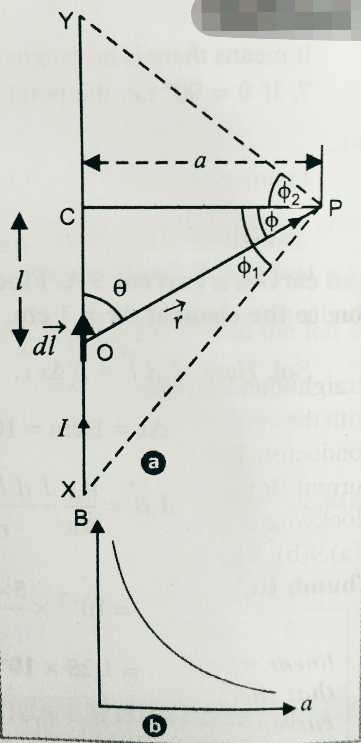
    Suppose  current ‘I’ is flowing through  a wire XY , and we have to find the magnetic field at point ‘P’.as shown in figure .


     B =  (µ0I/4Πa)(sinɸ1 + sinɸ2) ,

    Special cases – Case-(1) —  When the wire is of infinite length and point P is near the wire in that case                        ɸ1=900 , ɸ2=900 ;

    So magnetic field at that point P ,   B =  (µ0I/4Πa)(sin90 + sin90)  =  µ0I/2Πa

    Case-(2)–  When the wire is of infinite length and point P is near the  one end of the wire in that case                        ɸ1=900 , ɸ2=00 ;

    So magnetic field at the point P ,  B =  (µ0I/4Πa)(sin90 + sin0)  = µ0I/2Πa ;

    Case-(3)—If length of the conductor is finite (L) and point P lies on right bisector of conductor , then ɸ1=ɸ2= ɸ ; and sinɸ=L/( 4a2+L2)1/2 .

    Then magnetic field B= (µ0I/4Πa)(sinɸ + sinɸ)= (µ0I/4Πa)2sinɸ=(µ0I/4Πa)[ L/( 4a2+L2)1/2];

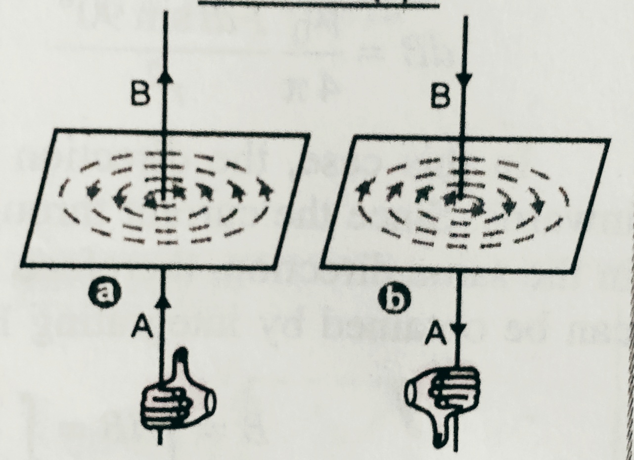
    Direction of magnetic field – The direction of magnetic field through a current carrying wire can be found using right hand thumb rule .

    Right hand thumb rule – According to this rule we held the current carrying straight wire in our hand grip of our right hand so that thumbs directed towards the direction of flow of current then the curled finger gives the direction of magnetic field around the conducting wire . As shown in figure.

    to see the video on Biot-Savart’s law click on the link given below-


  • What is Ampere circuital law

    What is Ampere circuital law

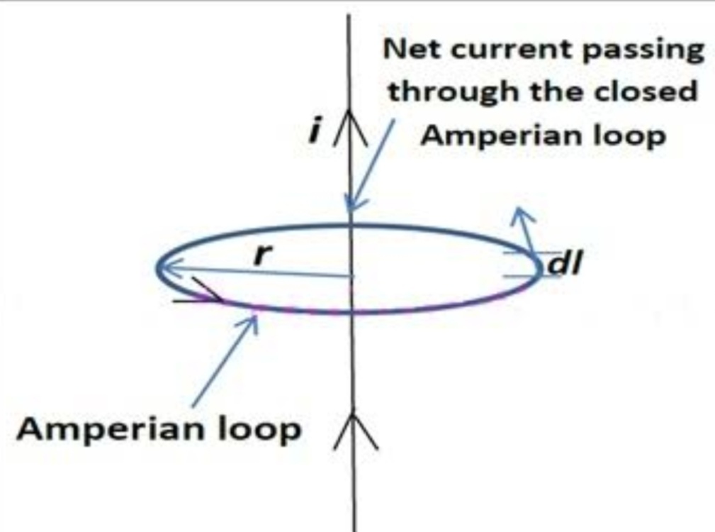
    Ampere circuital law – After the discovery of Oersted and Biot-Savart, Ampere found a useful relation between magnetic field and electric current.     [ In the case of all basic laws of physics , Ampere’s law can’t be derived , its validity is based on the correctness of the result.] . According to Ampere circuital law that the linear integral of magnetic field (B) along a imaginary closed path is equal to the product of current enclosed by the path and permeability of the medium µ0 . for a  long straight current carrying conductor  , magnetic field

                                                                        B= µ0 I/2ΠR

                                             So,  

                                      ∫B.dl =   ( µ0 I/2Πr) ∫dl    ( integrate with limit 0 to 2Πr )                                                      = ( µ0 I/2ΠR) × 2Πr = µ0I          


  • Physics Post 2

    Physics Post 2

    What is Lorem Ipsum?

    Lorem Ipsum is simply dummy text of the printing and typesetting industry. Lorem Ipsum has been the industry’s standard dummy text ever since the 1500s, when an unknown printer took a galley of type and scrambled it to make a type specimen book. It has survived not only five centuries, but also the leap into electronic typesetting, remaining essentially unchanged. It was popularised in the 1960s with the release of Letraset sheets containing Lorem Ipsum passages, and more recently with desktop publishing software like Aldus PageMaker including versions of Lorem Ipsum.

    Why do we use it?

    It is a long established fact that a reader will be distracted by the readable content of a page when looking at its layout. The point of using Lorem Ipsum is that it has a more-or-less normal distribution of letters, as opposed to using ‘Content here, content here’, making it look like readable English. Many desktop publishing packages and web page editors now use Lorem Ipsum as their default model text, and a search for ‘lorem ipsum’ will uncover many web sites still in their infancy. Various versions have evolved over the years, sometimes by accident, sometimes on purpose (injected humour and the like).

    Where does it come from?

    Contrary to popular belief, Lorem Ipsum is not simply random text. It has roots in a piece of classical Latin literature from 45 BC, making it over 2000 years old. Richard McClintock, a Latin professor at Hampden-Sydney College in Virginia, looked up one of the more obscure Latin words, consectetur, from a Lorem Ipsum passage, and going through the cites of the word in classical literature, discovered the undoubtable source. Lorem Ipsum comes from sections 1.10.32 and 1.10.33 of “de Finibus Bonorum et Malorum” (The Extremes of Good and Evil) by Cicero, written in 45 BC. This book is a treatise on the theory of ethics, very popular during the Renaissance. The first line of Lorem Ipsum, “Lorem ipsum dolor sit amet..”, comes from a line in section 1.10.32.