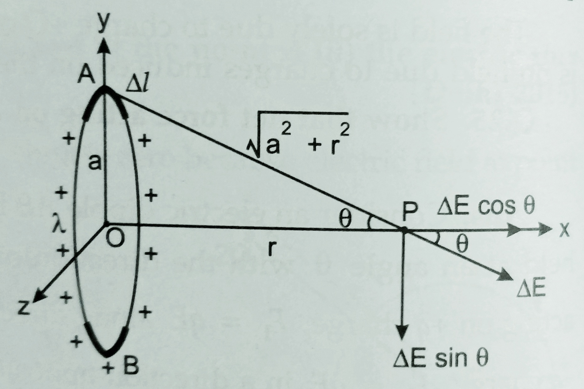
Expression for the electric field intensity at a point on the axis of the charged ring –
Question may be asked as ; A charge is distributed uniformly over a ring of radius ‘a’ . Obtain an expression for the electric field intensity E at a point on the axis of the ring. Hence show that for points at large distance from the ring behaves like a point charge.
Suppose a uniform circular ring of radius ‘a’ charged uniformly ‘Q’ which is distributed uniformly over the ring.
Suppose a small element ‘dl’ on the ring then, charge on the element is given by – dQ = (Q/2∏a) dl
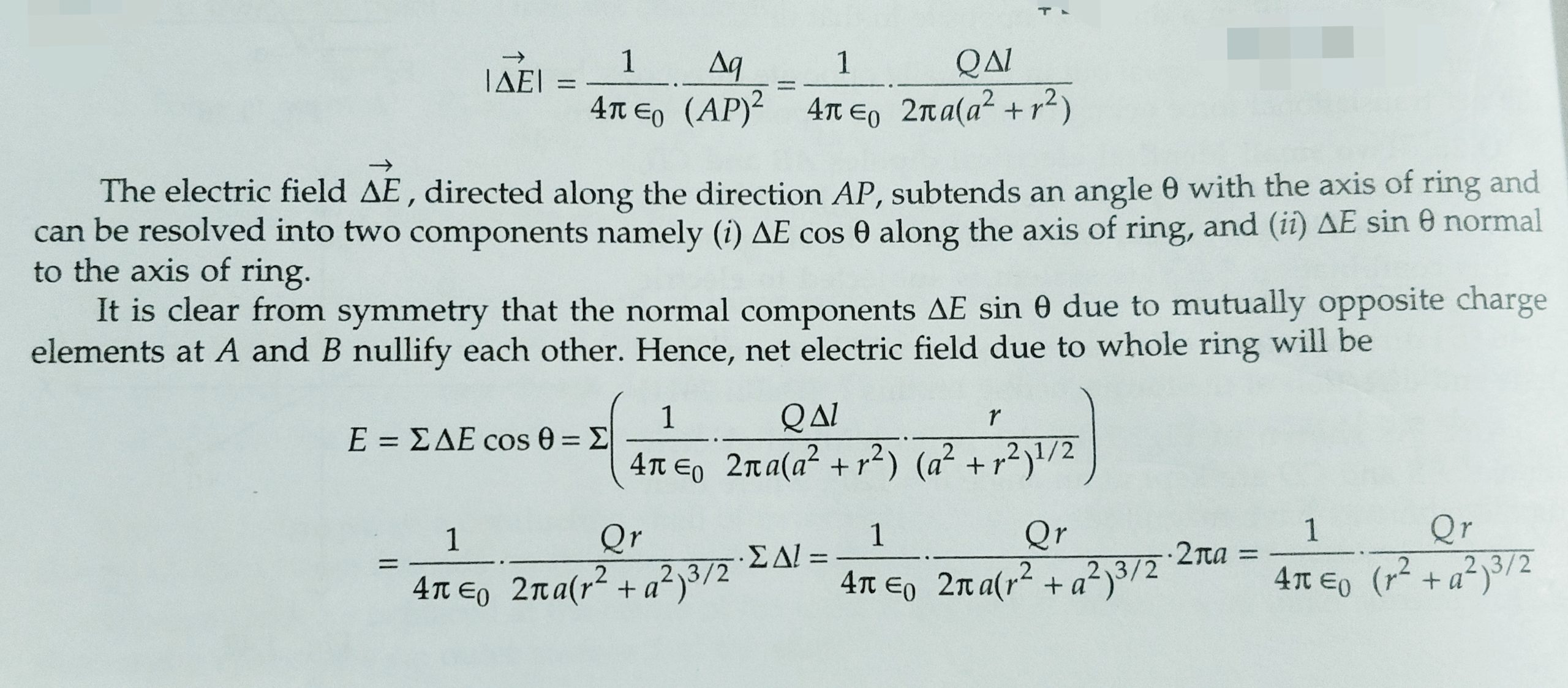
The electric field at point p due to this element is given by –
*****At the place of ∑ students can use integration with limit 0 to 2∏a ( in both case answer will be same ) *****
The field E is directed along the axis OP of the charged ring .
If r >> a , then the above expression may be written as ‘
E = (Q/4∏ϵ0 r2 ) . This shows that for far points at long distance from the ring , it behaves like a point charge .
To view the video of this topic electric field at a pint on the axis of uniformly charged circular link click on the link given below-
In this topic we will discuss about the , Expression for torque and potential energy stored in dipole placed in uniform electric field . and what will be Expression for torque and potential energy stored in dipole placed in non-uniform electric field ?
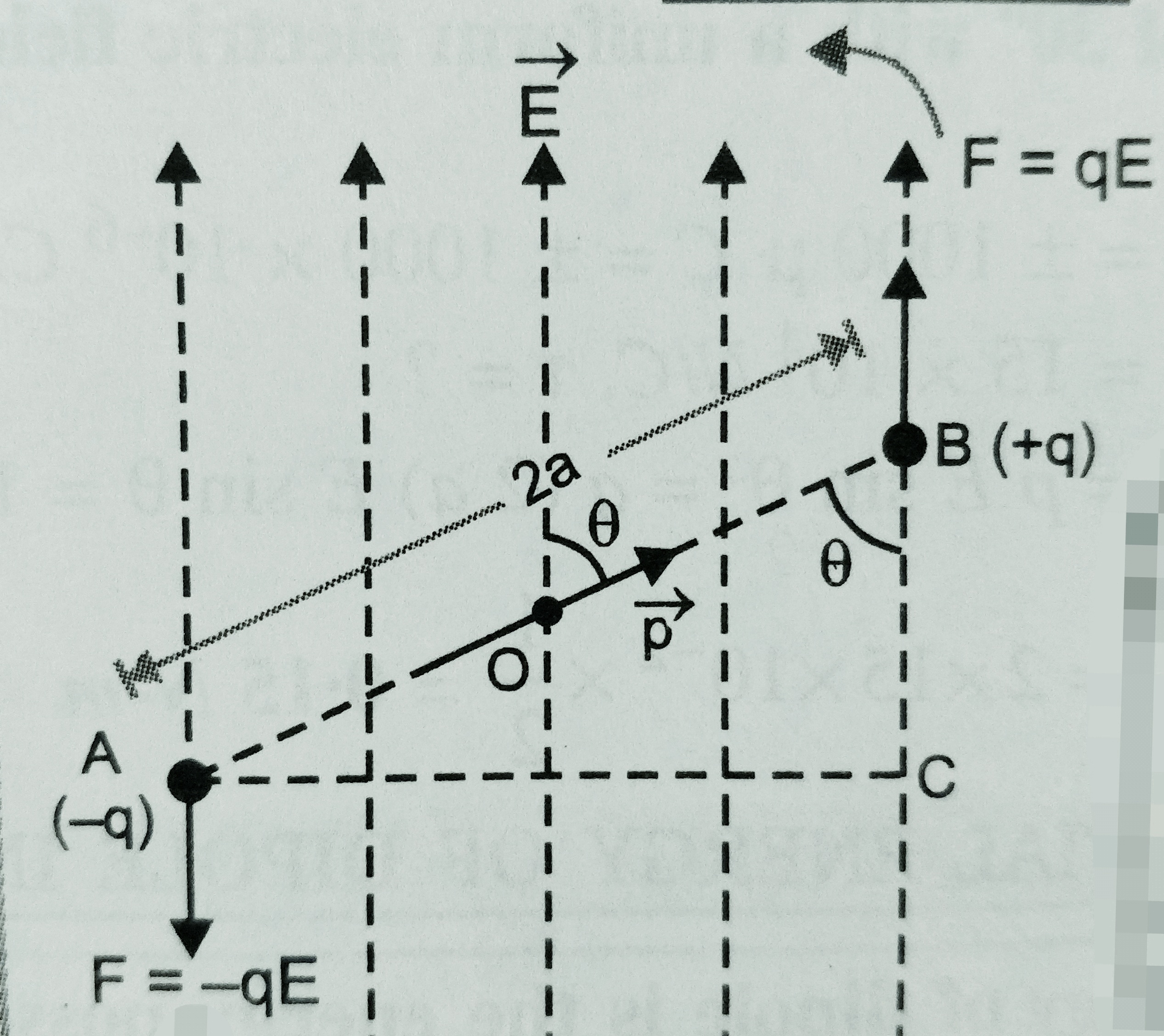
Suppose an electric dipole AB having charges -q and +q are placed at distance 2a , and dipole moment ‘p’ is placed in an uniform electric field ‘E’ .
Then Electrostatic force experienced on both the charges are F = q E , but the direction of forces on each charges are opposite to each other . since the electric field E is constant then net force on the dipole will be zero ( since forces are in opposite directions ) .
Since the forces are equal , unlike and parallel acting at different points so , they form a couple . The couple tends to align the dipole axis along the direction of field ‘E’ .
Let’s draw AC perpendicular on electric field ‘E’ .
But Questions may be asked by the students that ,what will happen if electric field is not uniform ?
then its answer will be that the net force on the dipole will not be zero (0) . It means there will be translational and rotational motion in the dipole . And net force will be equal to F1-F2 .
To view the video based on this topic torque and potential energy on the dipole placed in uniform electric field go to the link given below-
Electric dipole – An electric dipole consist of a pair of equal and opposite point charges separated by small distance .
Let two charges of equal magnitude but opposite sign( q and -q) are separated by distance 2a , then the arrangement is known as electric dipole .
Dipole moment (p) – Dipole moment of an electric dipole is the measurement of the strength of the electric dipole its magnitude is the product of magnitude of either charge and separation between them .
i.e. Magnetic moment p = q ( 2a )
Direction of magnetic field is given as negative to positive charge i.e. -q to +q ;
Its SI unit is C-m ( coulomb meter ) and dimension is [M0 L1 T1 A1 ] :
** Dipole field – It is the space around the dipole in which electric effect of the dipole can be experienced . For electric dipole electric field E α 1/r3 but for a point charge E α 1/r2
In the link given below , students can find the notes related to electric field at a point on axial and equatorial line due to a dipole.
To see the video of electric field at axial point due to a dipole click on the link given below
To view the video related to the topic electric field at equatorial point of a dipole click on link given below
Electric field intensity at any point due to a short electric dipole , it explain the electric field due to a dipole at any point and using this derivation we can find the electric field at axial and equatorial point of a dipole .
In this topic we will discuss about what is electric field and electric field lines , also electric field intensity at a point due to a point charge .
Electric field – Due to given electric charge it is the space around a charge particle in which electrostatic force can be experienced .
Electric field intensity – Electric field intensity at a point is the force experienced at unit charge placed at that point , it is strength of electric field at that point .
Electric field = F/q0
Electric field intensity due to a point charge – Suppose a charge Q is placed at point O , we have to find the electric field intensity at point p which is r distance away from charge Q .
Suppose a test charge q is placed at point p , then force acting at charge q due to Q is given as F = KQq/r2 ,
therefore electric field E = F/q
so, E =( kQq/r2 )/q
E = kQ/r2
If we have to find the electric field at a point due to group of charges then we can write
Net electric field, E = E1 + E2+E3 ..………..
Electric field lines – It is the imaginary line the tangent at any point on this lines gives the direction of force at that point .
To watch the video on electric field and electric field lines visit on given link below-
Properties of Electric field lines –
Electric field lines are continuous curve . They start from positive charge and end into negative charge . this is why electric field lines not form a closed loop . If there is a single charge then field lines start from the charge and goes into infinity .
2. Tangent to the electric field lines at any point gives the direction of electric field intensity at that point .
3. No two field lines intersect each other . This is because at the point of intersection , there will be two direction of force at the same point which is not possible .
4. The electric field lines are always normal to the surface of a conductor .
5. Where field lines are denser the electric filed intensity is more and vice- versa .
To watch the video of properties of electric field lines click on given link below-
***So in the form of electric field lines electric field intensity is equal to the number of field lines crossing normally a unit area around that point .
In this topic we will discuss about the Coulomb’s law of electrostatic force between two charged particle separated by some distance .
Coulomb’s law –
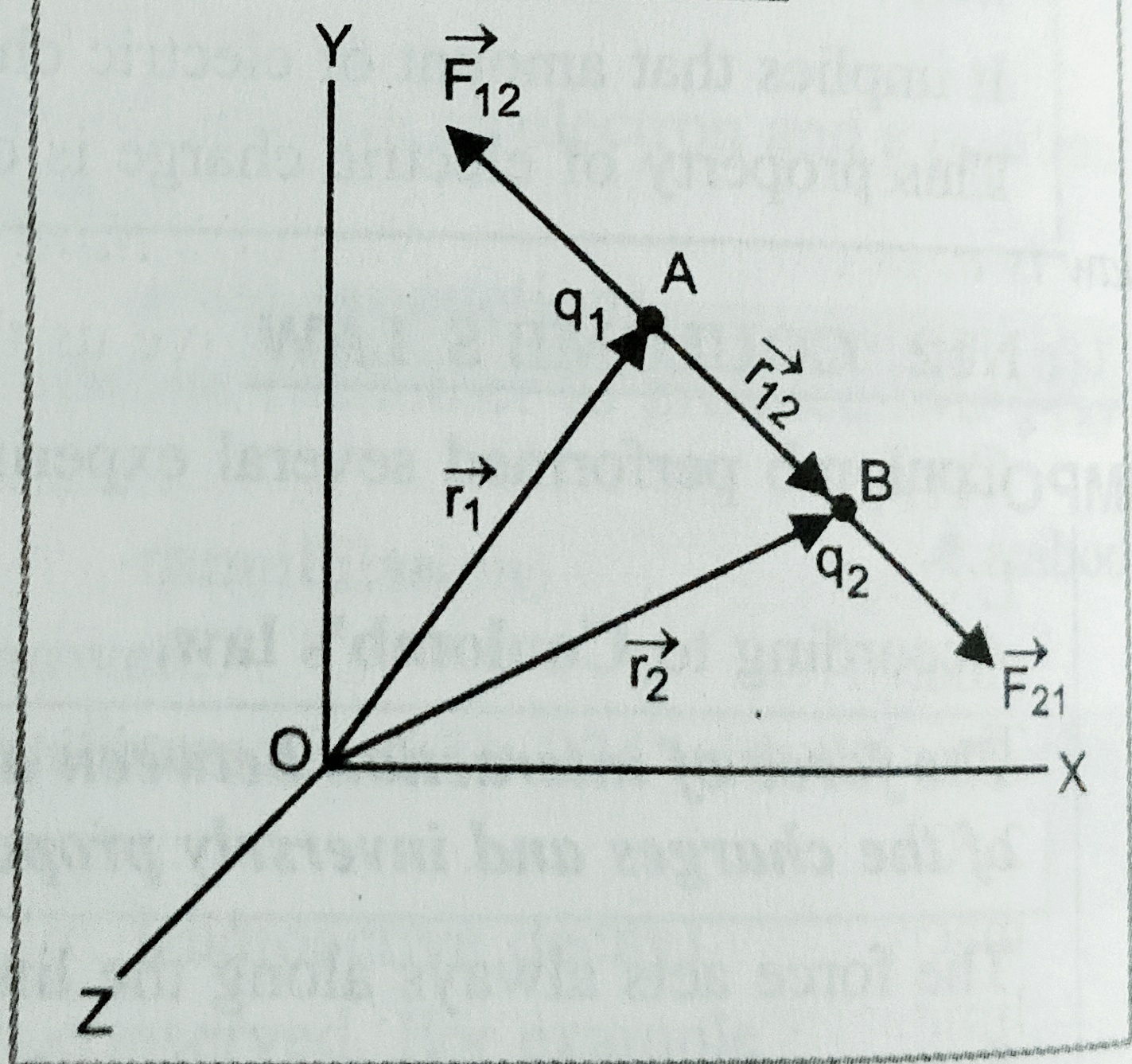
According to Coulomb’s law , the force of attraction or repulsion between two charged body is directly proportional to product of magnitude of their charges and inversely proportional to square of distance between them .
If Q1 and Q2 are two charges placed at distance ‘r’ from each other , then magnitude of force will be given as,
F α Q1.Q2 ………. (I) and
F α 1/ r2 …………(ii)
After combining these two we get
F α Q1.Q2/r2
Or F = K Q1.Q2/r2 where K is a constant given as
K= 1/4∏ϵ0 = 9 x 10⁹ here ϵ0 is called permittivity in vacuum or air .
ϵ0 =8.85 x 10⁻¹² C2‑N-1m-2
Electric permittivity of a medium is a measure of how the molecules of substance align or polarize under an electric field . The substance which has higher electric permittivity then its molecules polarization is maximum , and the more that substance resist the external electric field . It is denoted by ϵ . its unit is C2‑N-1m-2
Dielectric constant or relative permittivity – Dielectric constant of a given medium is the ratio of permittivity of the medium to the permittivity of free space (vacuum /air )
Or
Dielectric constant of a given medium is the ratio of force of interaction between two charges separated by a certain distance in vacuum/air to the force of interaction between two given charges at the same distance in that medium .
Dielectric constant K ( ϵr ) = ϵm / ϵo = F0 /Fm where ;
F0 = force of interaction between two charges separated by a certain distance in vacuum/air
F0 = force of interaction between two charges separated by a certain distance in the given medium
*Dielectric constant is unit less .
To watch the video of relative permittivity and charge density click on the link given below –
What is electric charge ? And what are the properties of charge ?
in this topic we will discuss that, What is electric charge ? And what are the properties of charge ? We will also discuss that what are the processes of charging of an objects ?
This topic will help the students of class 12th and 10th to understand the topic, What is electric charge and what are the properties of charge ?
What is electric charge ? how can we charge a body? And what are the properties of charges ?
Electric charges – Charge is the intrinsic property of the body which is possessed by the body itself , due to which electrostatic force comes into play .
There are two types of charge positive (+ve ) i.e. proton and negative (-ve ) i.e. electron which is given by the Benjamin Franklin .
Processes to charge a body –
Rubbing –
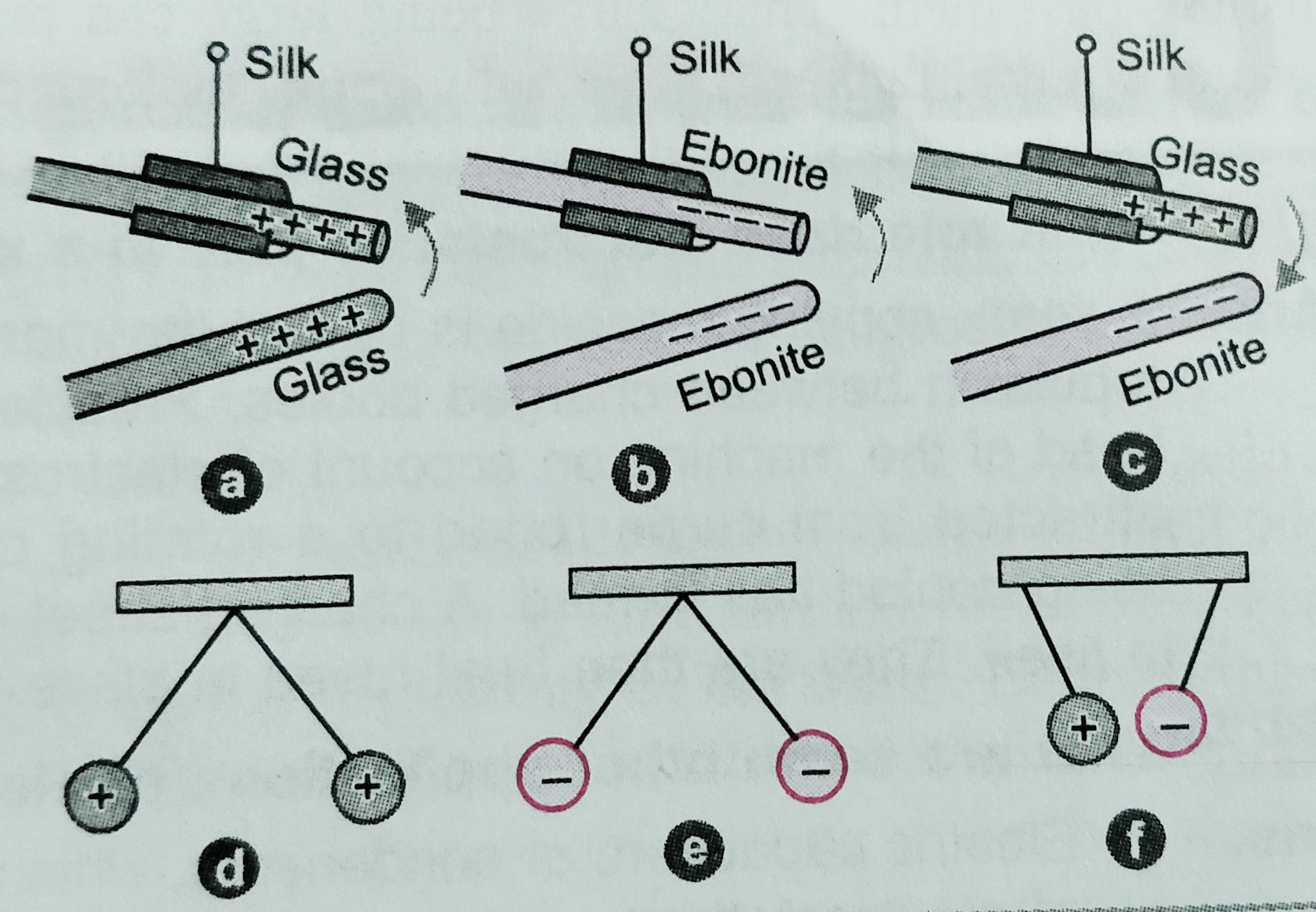
i) – A glass rod rubbed by a piece of silk brought closer to another glass rod rubbed by the silk cloth repel each other . But these glass rods attract the silk cloth with which it was rubbed . In this case the glass rods gets positive charge and silk cloths gets negative charge .
ii)- When an Ebonite / Amber rods are rubbed with a fur then Ebonite rod gets negative charge and fur gets positive charge.
Direct contact ( conduction)
iii)- When a pith ball is kept in contact with the rubbed glass or rubbed Ebonite rod pith balls get same kind of charge with which it is connected .
It can be understand with the help of following figure-
charging of bodies
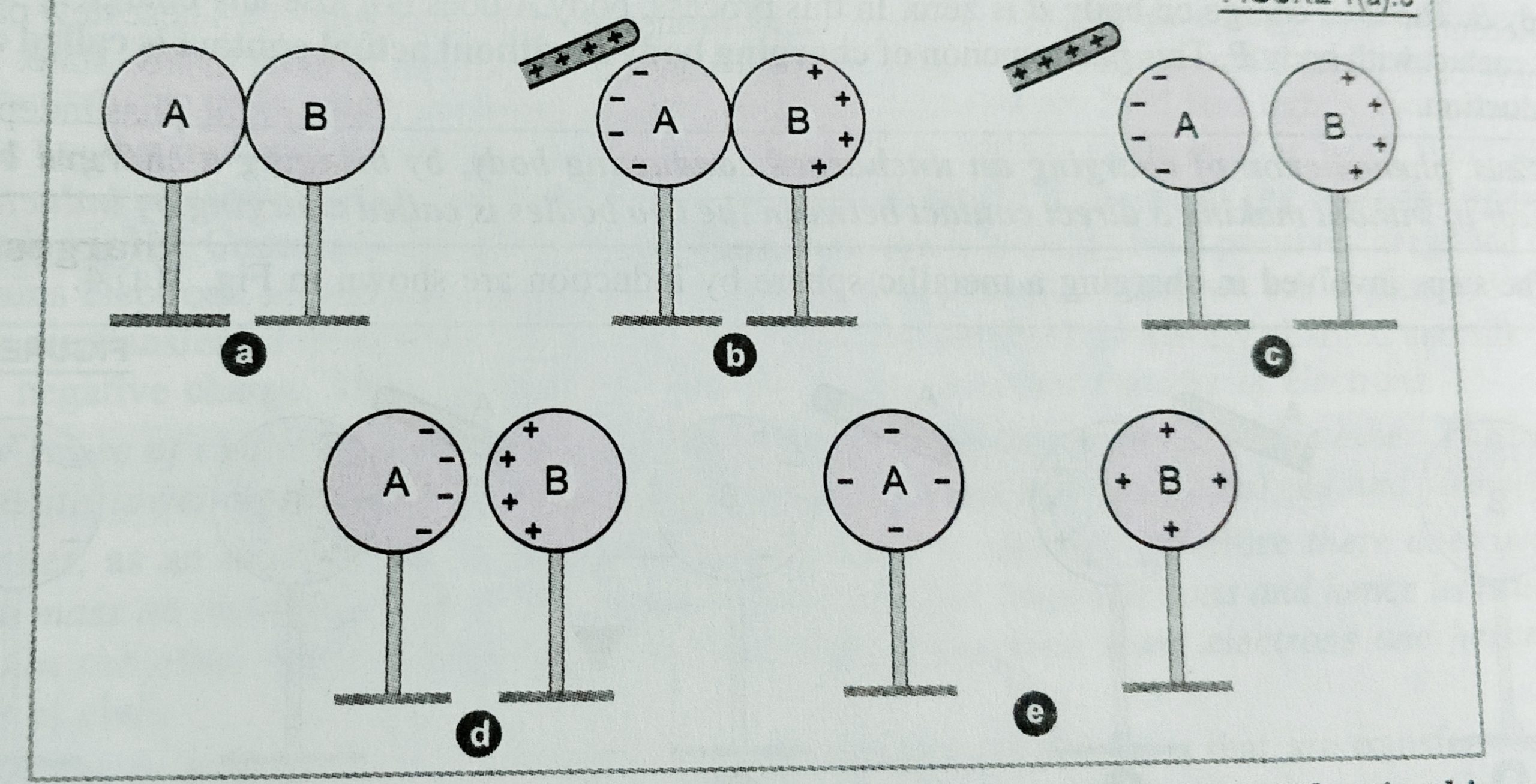
Induction – when a charge body ‘A’ is kept near an uncharged body ‘B’ then some charge of opposite sign appears on the near face of body ‘B’ , and equal charge of opposite sign is appear on the another face of body B . so we can say the process of charging of a body without actual contact is called induction .
Let us understand how can we charge a body by induction ; Suppose a positively charged glass rod is kept near an uncharged body ‘B’ , then free electrons of B comes on the surface near the body A but positive charge appear on the opposite face ( because sphere on whole remain neutral ) as shown in fig. again when the sphere B is grounded then electrons move from ground towards the sphere which neutralise the positive charge on the other side of the sphere . The negative charge at the near end remain on the sphere , and when rod A is removed the negative charge appears on the complete sphere . And finally body B gets negatively charged .
charging a body due to induction
Similarly we can see in fig. how can we charge two spheres by induction .
To view its video click on the video link given below –
Properties of charges –
When we see the several experiments carefully we will come to know that the following properties shown by the charged bodies –
(A) Like charges repel and unlike charges attracts , which is finally explained by the Coulomb . According to Coulomb’s The force of repulsion or attraction between charged body is directly proportional to the products of magnitude of charges and inversely proportional the square of the distance between the charged body .
(B) Quantisation of charge – It is the property of the charged particle due to which , the charge on a body is integral multiple of basic unit of charge i.e. electron (-e) or proton (+e) . It is given that charge on a body Q = n. e : where n is the integer . and e= 1.6 x 10⁻¹⁹ C .
( C ) Additivity of charge – It is the property of charge by virtue of which total charge of a system is obtained simply by adding algebraically all the charges present in the system . If q1 , q2 , q3 …… are the charges on the particle of the system then total charge on the system q= q1 + q2 + q3………. We should use proper sign of the charge during the addition of charges .
(D) Conservation of charge – According to this property total charge of the isolated system always remain constant . i.e. charge neither be created nor be destroyed but it can transfer from one body to another . When we rub a body then equal number of charges of opposite sign appear on the surfaces of these bodies .
To view its video click on video link given below –
What is diffraction of light ? conditions for maximum and minimum using single slit experiment, and intensity curve .
Diffraction of light –
When a beam of monochromatic light passes through an aperture or an obstacle comes into the way of light then light is bent at the corners of the aperture or obstacle , this phenomena of light is called diffraction of light
Diffraction of light at a single slit – when a beam of monochromatic light is made incident on single slit , then we get diffraction pattern on the screen , which contain bright (maximum) and dark (minimum) band .
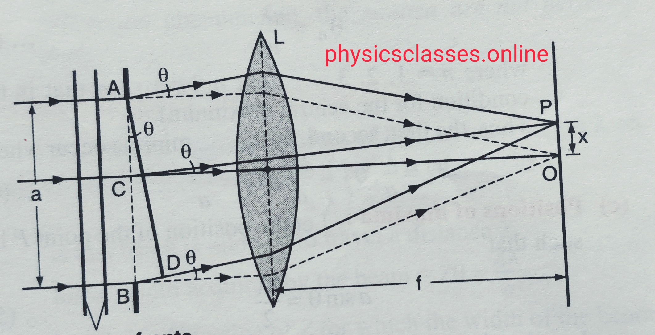
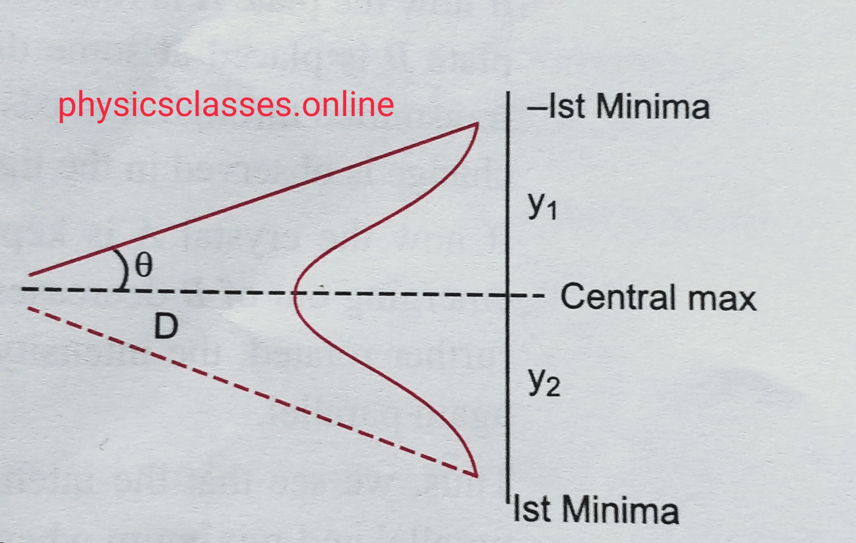
diffraction single slit
Let, AB be a slit of width ‘a’ and parallel beam of a monochromatic light incident on it . All the primary ray incident converges at the center and form a bright fringe, and all the secondary wave gets superimposed and form secondary dark and bright fringes on the screen .
Let θ be the angle of diffraction for waves reaching at point P of screen , and AD is the perpendicular drown from ‘A’
The path difference between the rays AP and BP
So path difference , p = BP – AP = BD
But from geometry <ANB = θ
Sinθ= BD/AB ,
Or, BD = AB sinθ
width of the slit AB = a
Hence path difference ; p = a sinθ ……………………………(i)
Position of central maximum – the wavelets fall on the lens L along parallel direction of the axis reaches at o in the same phase and form central maximum .
Position of secondary minimum – if we imagine the slits is divided in two equal halves AC and CB then every point on the upper half the path difference is λ/2 and same as in lower half . they will reach at the point p in opposite phase and form destructive interference cause of minimum or dark band , for dark band a sinθ = nλ , where n= 1,2,3,4………..
, if θ is very small then , aθ = nλ
So , θ = nλ/a .
Position of secondary maximum – we imagine slits is divided in three equal parts so the path difference between these two upper parts will be λ/2 , which will cancelled each other effect , so only third part will be the cause of the diffraction pattern obtained on the screen .
So , a sinθ = ( 2n+1) λ/2
If θ is very small then , a θ = ( 2n+1) λ/2
So , θ =( 2n+1) λ/2 / a
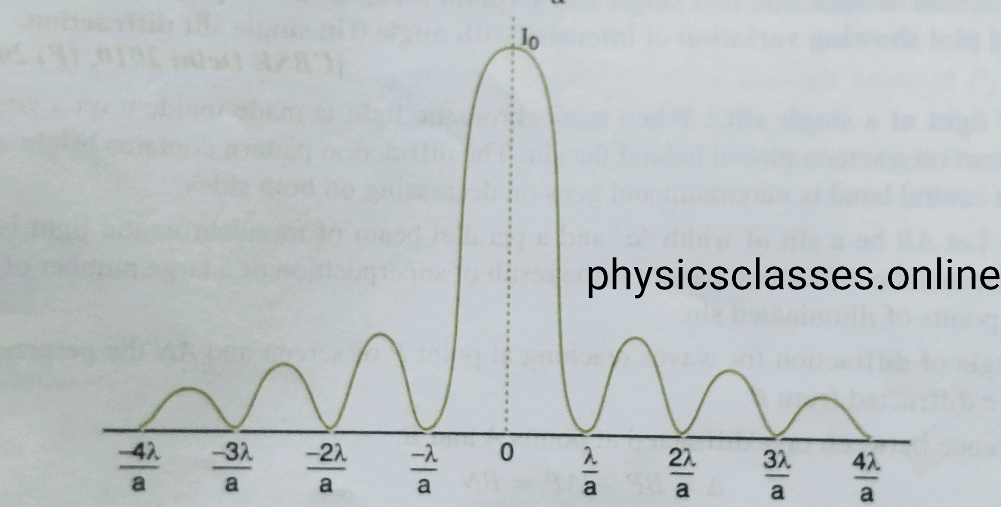
Intensity- position curve for diffraction of light
Central maximum is twice the width of any other secondary maximum –
diffraction central maximum
For first minimum , from the relation of secondary minimum θ = nλ/a
Here value of n=1 ( for first minimum ) , so, θ = 1λ/a .
But , according to the geometry θ = y1 / D ( where D is the separation between the slit and screen ) .
Angular width of the central maximum 2θ = y1 + y2 /D ,
Or, 2λ/a = y1+ y2 /D,
Or , Y1 + y2 = 2λD/a
Therefore , width of the slits = 2( λD/a) = 2 x (width of other secondary maximum).
Questions based on diffraction of light – What do you mean by the term diffraction of light ? using single slit show the conditions of central maximum, secondary minimum, secondary maximum and hence draw the intensity curve with position ‘x’ . Using single slit experiment show that (i) the intensity of diffraction fringes increases as order (n) increases .(ii) angular width of the central maximum is twice of first order secondary maximum .
For important questions based on the chapter wave optics– click here
What is em wave ? how it is produced ?and all kind of feature are explained here.
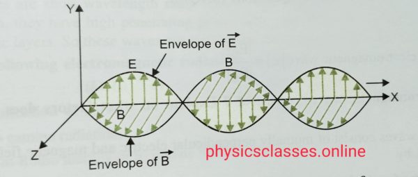
The propagating in space through electric and magnetic field varying in space and time simultaneously are called electromagnetic wave .
Origin – The electro magnetic wave are produced by an accelerated and deaccelerated charge or LC circuit . T he frequency of the electromagnetic wave is ѵ = 1/2Π √LC .
Characteristics of em wave –
The electro magnetic waves is produced in free space with speed of light
em waves are neutral , so they are not deflected by electric and magnetic field .
The em waves shows the properties of reflection, refraction , diffraction and polarisation.
In em wave the electric and magnetic field are always in the same phase .
The ratio of electric field and magnetic field in free space is constant which is equal to velocity of light ( c ) i.e. E0/B0 =1/√µ0ϵ0 =C=3 X 10⁸ m/s .
In an em wave the energy is propagated by means of electric and magnetic field vectors in the direction of propagation of wave .
Maxwell’s modification of Ampere’s law and displacement current –
According to Ampere’s the line integral of magnetic field for a closed path is µ0 times the total current passes through the closed loop. i.e. ∫B. dl = µ0 I but Maxwell modified the law and, dc according to him ∫B. dl = µ0 (I + ID) Where Id is the displacement current.
displacement current
Displacement current – It is the current which come in the existence due to the rate of change of electric flux with respect to time
As we know I = dQ/dt but between the plates of the capacitor ,
Electric field E = Q/ A ϵ0 and hence Q = E A ϵ0 = ɸ0 ϵ0 (WHERE ɸ0 = electric flux)
But, I = dɸ0 /dt = ϵ0 dɸ0 /dt.
So we can write improved form of Ampere’s law ∫ B. dl = µ0 ( I + ϵ0 dɸ0 /dt ) .
Consequences of displacement current –
(a)with the discovery of displacement current the law of electricity and magnetism become more symmetrical then before .
(b) since the displacement current is produced by time varying electric field , an important link between electric field and magnetic field established .
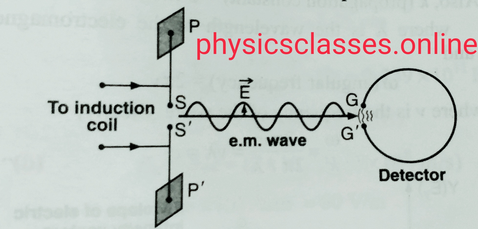
Hertz’s experiment – Hertz demonstrated the production and detection of electromagnetic wave by electrical means . Experimental arrangement used by Hertz shown in figure :- S and S’ are the two spheres connected by two large metal plates P and P’ , the spheres are connected to an induction coil . By causing a discharge between the spheres , the current distribution between the plates is such that an electromagnetic wave is generated parallel to the gap SS’ . the radiation thus produced is detected by Hertz by using an open wire loop . the em wave reaches at the gap GG’ of the detector has an electric field is enough the establish a high potential difference between this gap and cause a spark .
Hertz experiment
When the detector gap GG’ is at right angles to the right gap SS’ , no electromagnetic radiation detected , the sensitivity is maximum when the gap GG’ is parallel to SS’ . this property explain the transverse nature of the em wave , and em wave propagate perpendicular to the direction of propagation of electric field .
Speed of electromagnetic wave in vacuum –
According to faradays law of electromagnetic induction
∫E. dl = – dɸB /dt ………..eq.1
And according to Ampere-Maxwell’s law , ∫B. dl =µ0 I + µ0 ϵ0 dɸE /dt …………………..eq.2
[ ɸB Flux for magnetic flux and ɸe is the electric flux .]
For a plane polarised em wave travelling in the X- axis eq 1 and 2 gives
dEy /dx = -dBZ/dt .
or , dE/dx = – dB/dt ………………………eq. 3
and , dBZ/dx = -µ0ϵ0 dEy/dt .
or , dBx /dx = – µ0ϵ0 dE/dt ………………………eq. 4
taking the partial differentiation of eq 3 we get
d(dE/dx)/dx = – d(dB/dt)/dx = – d(dB/dx)/dt .
or d2E/dx2 = -d(-µ0ϵ0 dE/dt)= µ0ϵ0 d2 E/dt2……………..eq. 5
similarly ,
d2B/dx2 = µ0ϵ0 d2 B/dt2 ………………………………..eq. 5
on comparing eq 5 and 6 we get with the general equation of wave
d2y/dx2 = (1/v2) ( d2y/dt2) where v is the speed of wave .
we get 1/v2 = µ0ϵ0 and hence ,
we can write , v = 1/√ µ0ϵ0 or velocity of light in vacuum c = 1/√ µ0ϵ0 .
Relation between electric and magnetic field with the speed of electromagnetic wave -the varying electric and magnetic field of a plane electromagnetic wave travelling along X- axis is given as ,
Ey = E0 sin (kx-ωt) ………………………………………eq. 1
Bz= B0(kx-ωt) ………………………………………………..eq.2
Here , k = 2Π/λ
ω =2Πѵ ,
Clearly , ω/k = 2Πѵ/ (2Π/λ) = ѵλ = c .
dE/dx = kE0 cos(kx-ωt)
dB/dt = – ωB0 cos (kx-ωt)
dE/dx = -dB/dt
kE0 cos(kx-ωt) = ωB0 cos(kx-ωt)
KE0 = ω B0 .
E0/B0 = ω/K = c ……………….this is the req. relation
Intensity of electromagnetic wave – it is the amount of energy crossing per unit time per unit area perpendicular to the direction of propagation of electromagnetic wave .
Let us consider there is a cylindrical region through which electromagnetic wave passing as wave is perpendicular to its area of cross-action , A is the area of cross-action and l is the length of the cylinder , then volume of cylinder V = Al
Total energy of the cylinder ; E= U.x Volume = U Al
Intensity I = total energy / (time x area) = U Al/ [(l/c) x A]= U X c
Since U = ½ ϵ0E02 , therefore intensity I = ½ ϵ0E02 c = ½ ϵ0Erms2 (√2)2 c = I = ϵ0 Erms2 c .
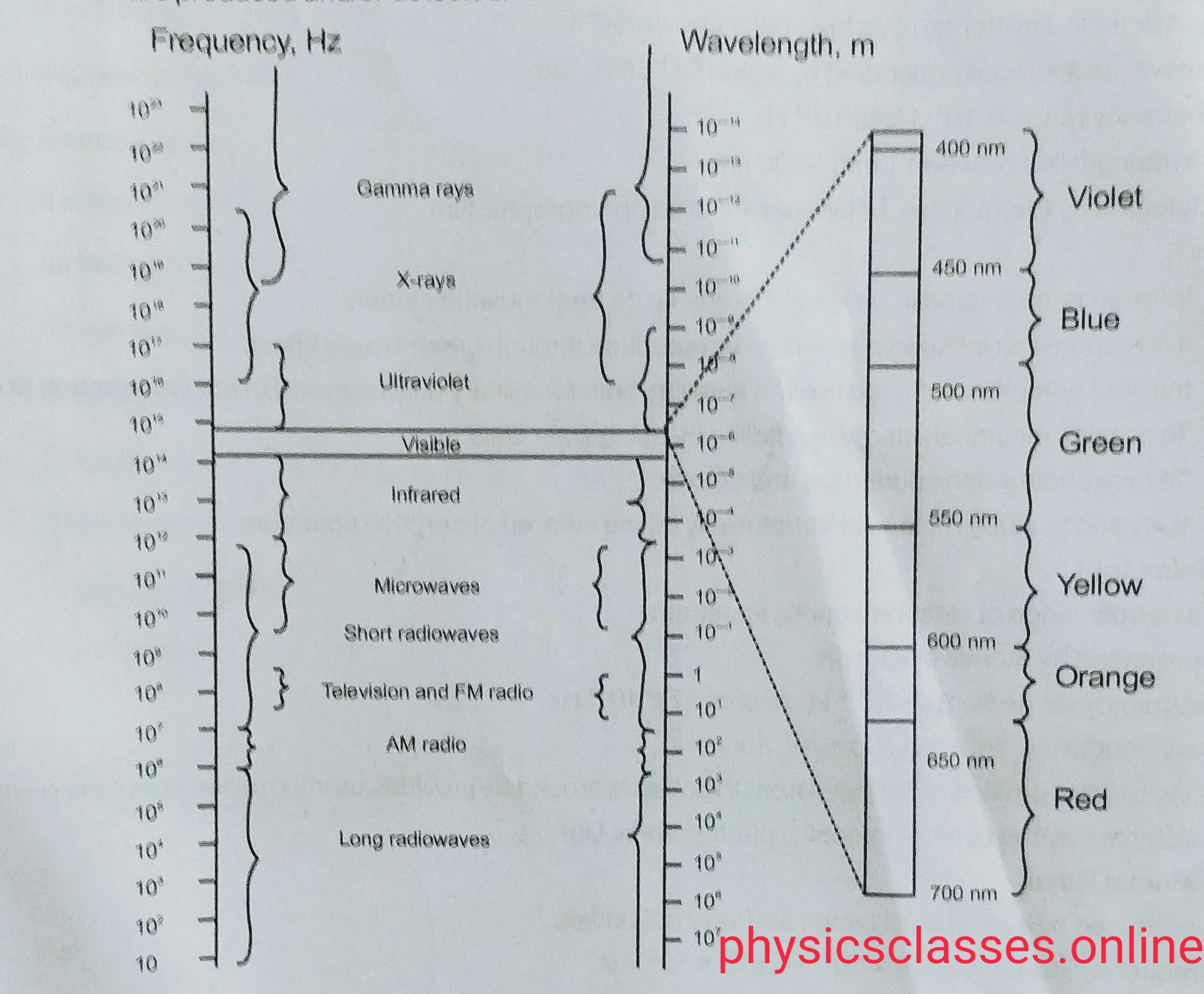
“ The orderly distribution of electromagnetic radiation according to there frequency / wavelength is called electromagnetic spectrum .”
em wave spectrum
Radio wave – It is produced by the accelerated motion of charges in conducting wire or we can say by oscillating electric circuit .
Its frequency range is 500kHz – 1000MHz , wavelength range is 10-2m – 104m. it reflects , refract and diffract . it is used in radio and t.v. communication.
Microwave – It is produced by special vacuum tube known as klystrons ,magnetrons . its frequency range is 1GHz – 300GHz . It is used as radar system for aircraft navigation , detect the speed of cricket ball, automobile etc. its another use is in microwave oven .
Infrared waves – it is produced by hot bodies i.e. vibration of atoms and molecules . Human eye can’t detect it but snake can detect it . These wave is absorbed by water , co2 and NH3 . Its frequency range is 1011Hz-1014Hz and its wavelength is between , 1mm-700nm . It can be detected by infrared photographic film . it is used to treat muscle strain (physical therapy), green house effect, satellite for military purpose and to observe growth of crops, to provide electrical energy in the satellite by using solar cell , to take the photograph during fog and smoke and it is used to study molecular structure.
Visible light – It is produced by atomic excitation . Its frequency range is 4x 10¹⁴Hz -7x 10¹⁴Hz. , its wavelength lies between 700 nm – 400 nm . It makes the thing visible .
Ultraviolet ray – It produced by sun , special lamp and very hot bodies . Its frequency lies between 8 x 10¹⁴ Hz – 5 x 10¹⁶ Hz. Its wavelength lies between 400 nm – 0.6 nm . it is detected by photocell and photographic film . It causes the harmful effect on human being. It is used in eye surgery , kill germs in water purifier , to kill the bacteria , in finger print technology.
X- ray – It is produced in a tube called modern X-ray tube . its frequency range is between 1016 Hz – 1021Hz . its wavelength lies between 10nm – 10-4nm. It is used as a diagnostic tool in medicine and treatment of certain forms of cancer , in engineering it is used to detect cracks and holes , defect in rubber tyre and gold .
Gamma rays – it is produced in nuclear reaction they are emitted by radioactive nuclei , its frequency range is 1018-1022Hz . its wavelength is less than 10-3nm. It is detected by photographic film , Geiger tube , ionisation chamber. They shows phosphorescence , fluorescence ,polarisation , diffraction. It has very high penetrating power . it is used for cancer therapy, and it provide important information regarding nuclear structure.
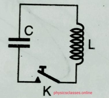
An LC circuit consists an inductor and a capacitor connected in parallel . Its another name is tank circuit.
Working –
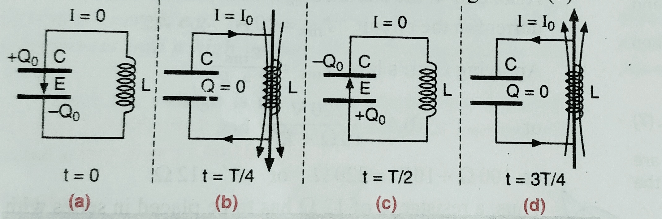
At t= 0 – – capacitor is first charged . The whole energy is stored in the capacitor which is U= ½ CV2 , at that instant charge on the capacitor is Q , and there is no current through the circuit and energy in the inductor at that instant is zero .
At t=T/4 (T= time period of oscillation ) – – the capacitor begins to discharge and a growing current starts flowing through the inductor , which setup magnetic field around it which produces induced current in the inductor in opposite direction and hence there is delay in discharge . As the capacitor discharges its energy starts decreasing which converted as magnetic energy in the inductor , and at an instant total charge in capacitor is zero , and hence energy stored in the capacitor is zero and energy stored in the inductor at that time is ½ LI2‑.
At t=T/2 – as soon as capacitor is completely discharged , the magnetic field around the inductor starts decreasing , it produced an induced emf in opposite direction , due to which capacitor start charging it self in opposite direction and at an instant inductor discharged completely and capacitor charged completely again which is ½ CV2 .
This process repeated again and again then energy obtained once keep on oscillating between capacitor and inductor and to and fro pulses of current are produced .
LC-OSCILLATOR
WORKING OF LC-OSCILLATION AND DERIVATION OF ITS FREQUENCY – Watch Video Below
Derivation for frequency of LC- oscillation
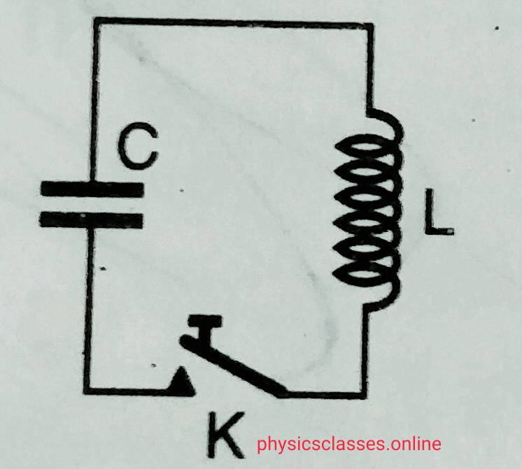
– Suppose an electrical circuit having a capacitor of capacitance C and an inductor of inductance L connected as shown in fog. Below-
LC OSCILLATION
. Let the capacitor is charged Q initially and when key is closed emf induced in the inductor is L (di / dt) and potential difference across the capacitor is Q/C . Then from Kirchhoff’s law L (dI/dt) +Q/C =0 ………..(i)
But I = dQ /dt
And hence eq. (i) may be written as
L(d2Q/dt2)+ Q/C =0
Or , d2Q/dt2 + Q/LC = 0 ………………………..(ii)
But as we know eq . of SHM. May be written as d2x/dt2+ ω2x = 0 ………..(iii)
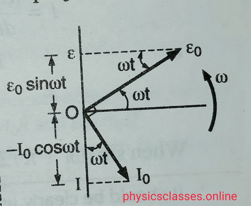
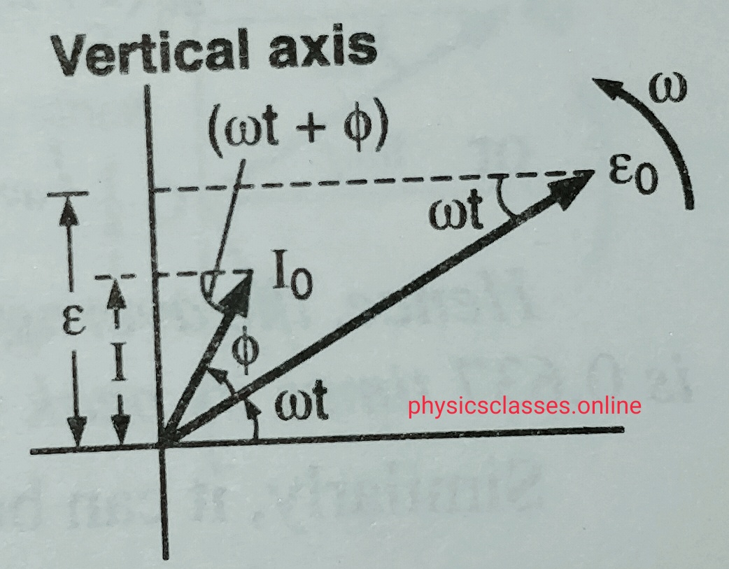
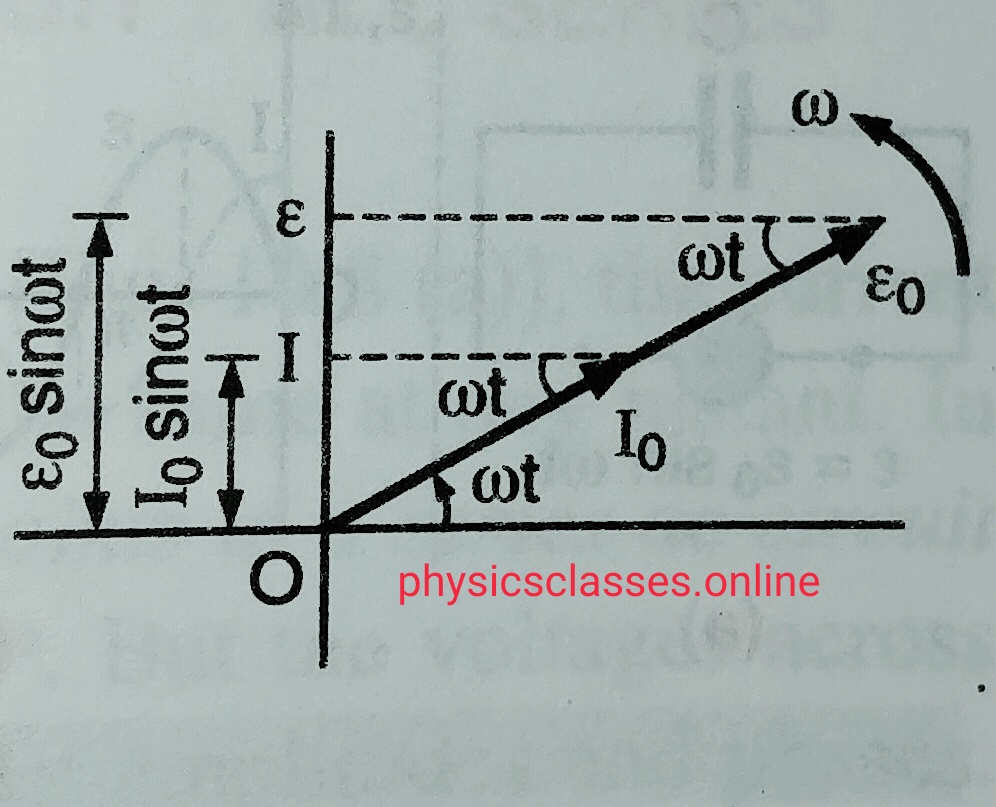
The co-planar vectors which represents sinusoidal time varying quantities like alternating current or alternating voltage are known as phasor and the graphical representation of these quantities for the ac circuit is known as phasor diagram.
In another words we can say when AC or alternating voltage represented as rotating vectors in a graph is known as phasor diagram .
Phasors are represented by the arrows rotating anticlockwise .
The length of the arrow represent the peak current or peak voltage.
Phasor diagram represents the phase relation between alternating current and voltage
Representation of phasor diagram for an ac source-
PHASOR DIAGRAM-1
Phasor diagram when ac circuit containing only resistance –
PHASOR DIAGRAM -2
Phasor diagram when ac circuit containing only capacitor-
PHASOR DIAGRAM -3
Phasor diagram when ac circuit containing only inductor-