In this post we will discuss about the graph , and how graphs makes to understand the physics easily ?
Graph-
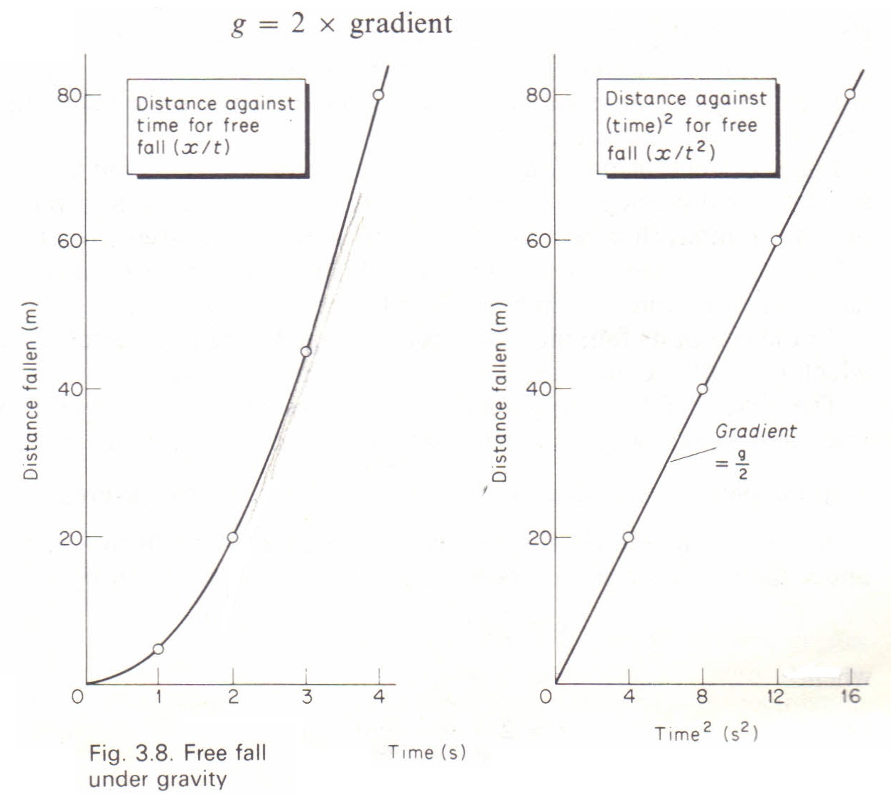
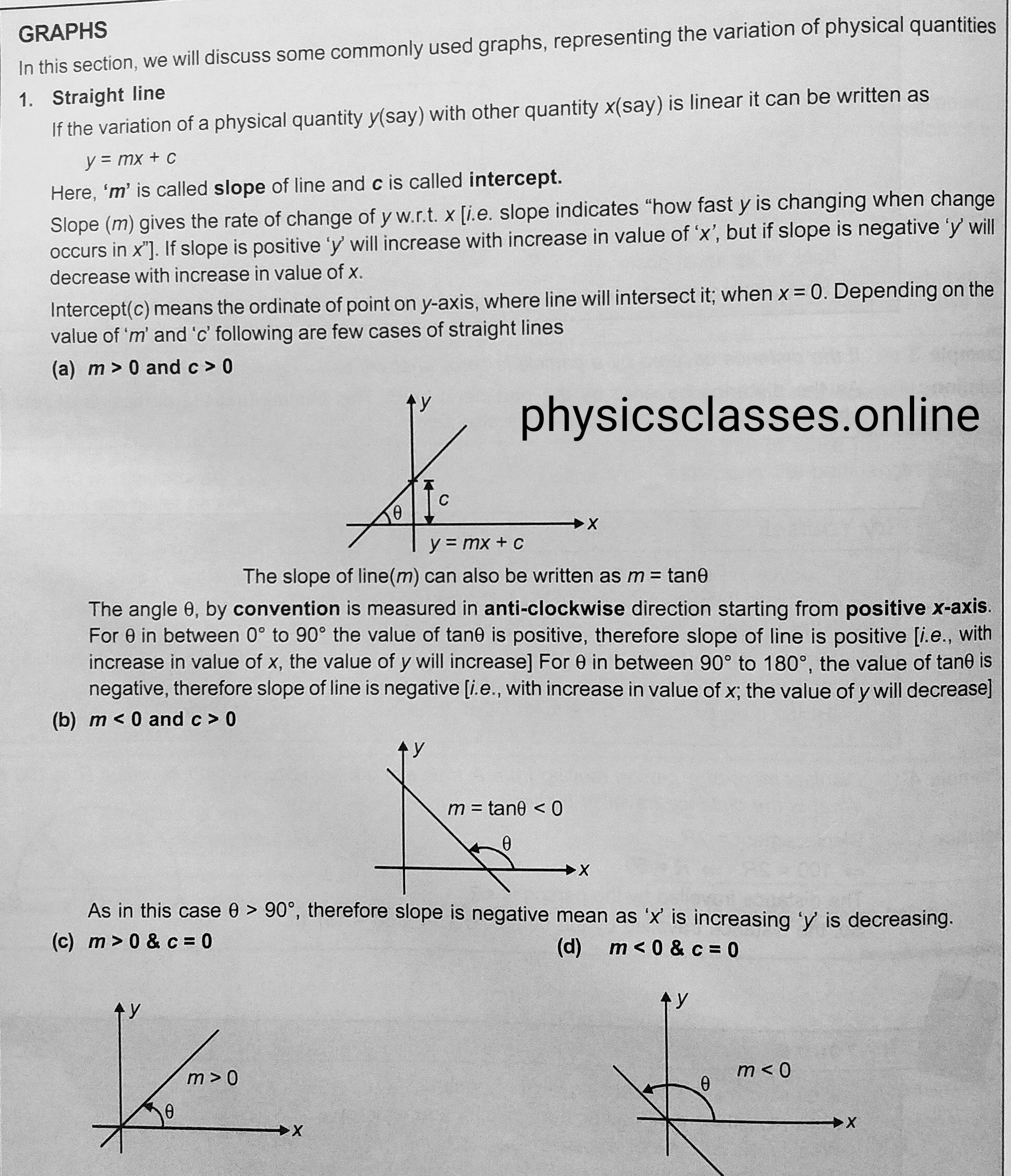
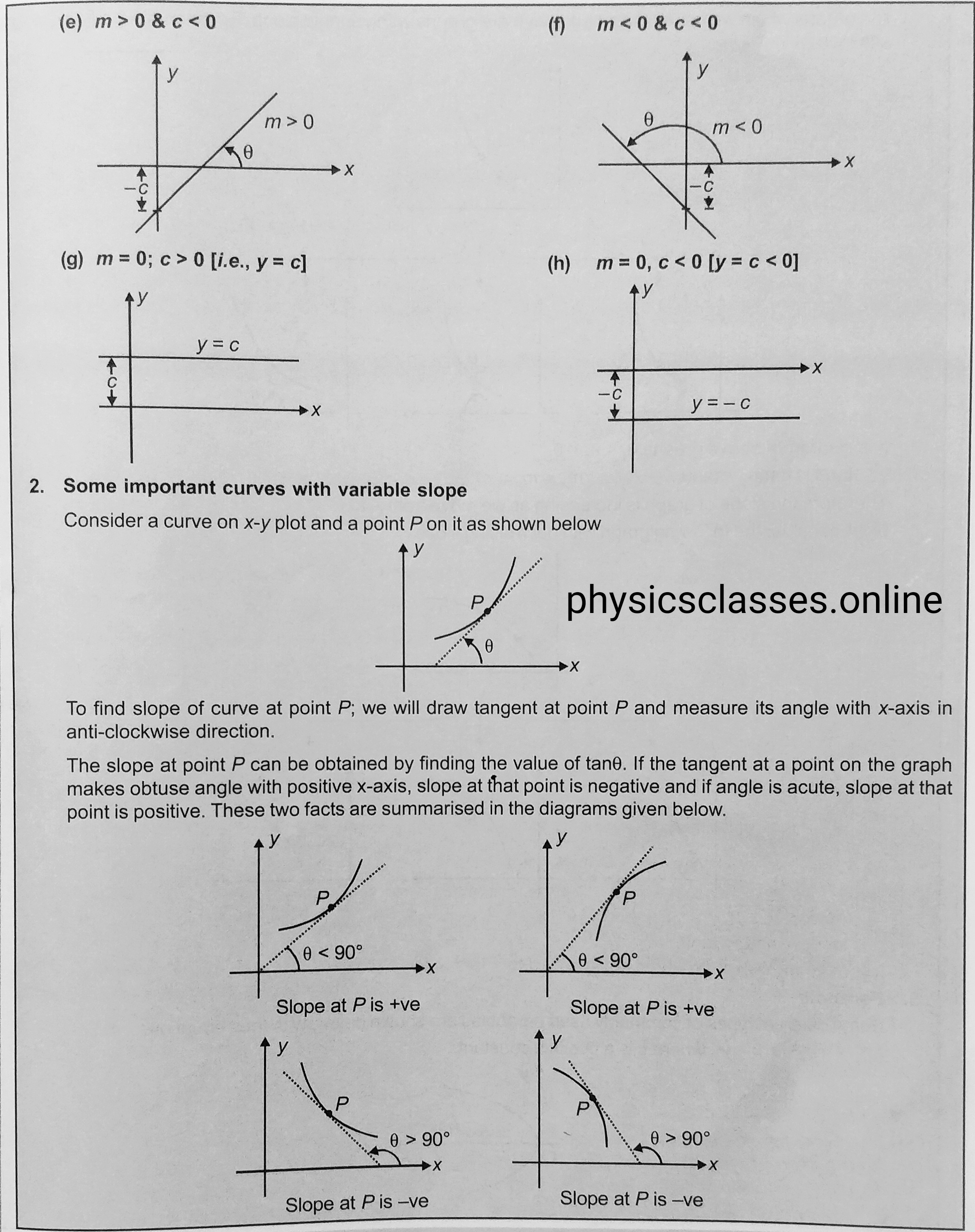
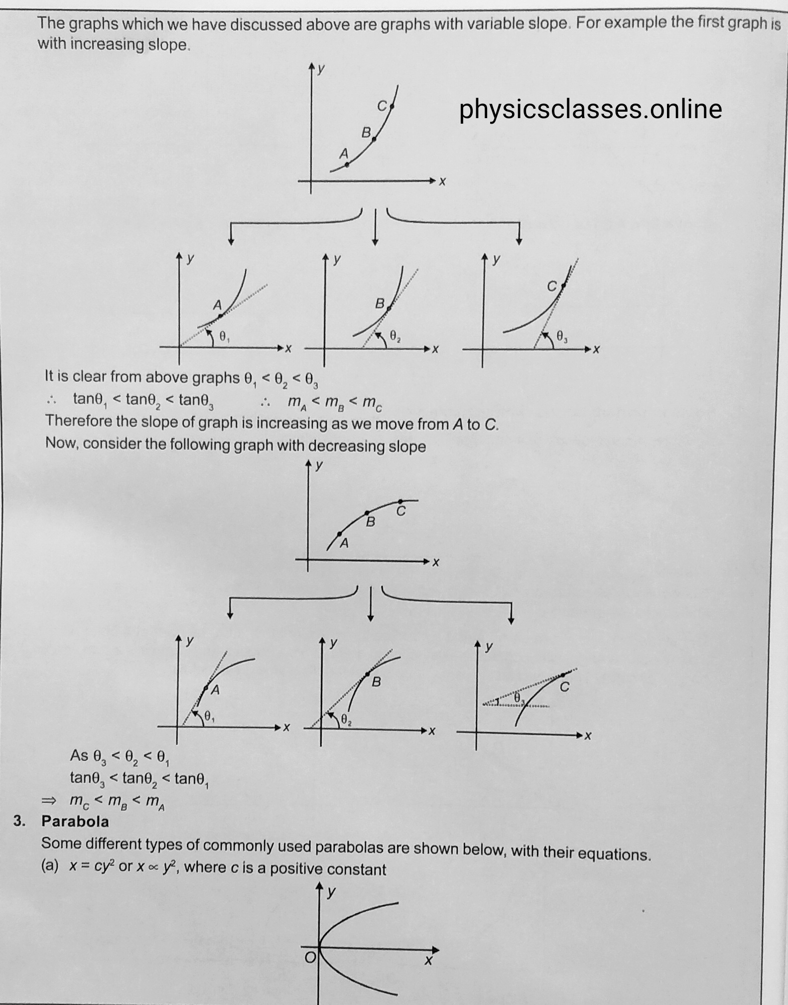
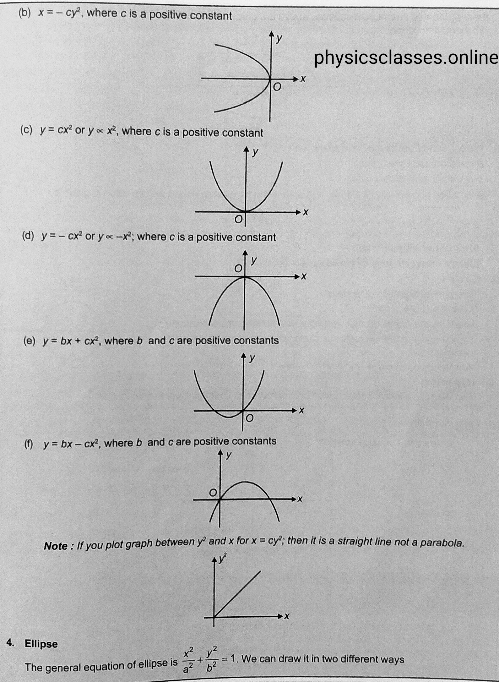
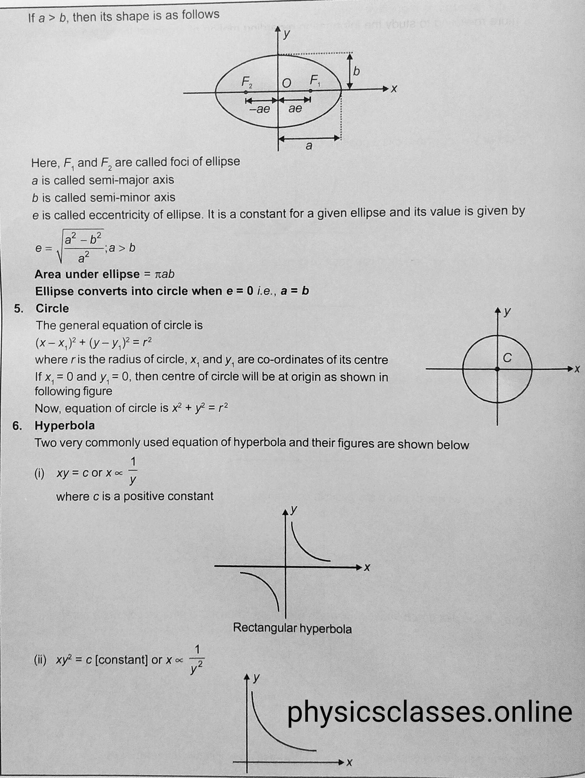
As we know it is not easy to study or understand the physics. Students who is taking interest in physics and want to understand the physics, it is necessary to improve your mathematics and most importantly graph, students who can’t solve the graphical questions will face lot of difficulties. So I am trying to provide some information/ knowledge for the students, so that students can understand the graphical questions easily. Now these days questions based on graph is important for every topics of physics specially the students who is appearing in the JEE/ NEET examination. Graph makes the calculation easier and it makes the topic to understand more easy. So every students must have to understand the graph and solve the questions based on it.
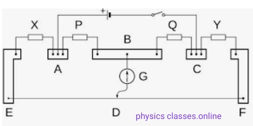
Question based on meter-bridge may be asked as ; What is meter-bridge ? How does it work? find the expression to find the value of unknown resistance using meter bridge.
Meter-bridge is a devise used to know the value of unknown resistance.
In this topic we will derive the expression for coefficient of mutual induction or mutual inductance of two coaxial solenoid
MUTUAL INDUCTION OF TWO COAXIAL SOLENOID–
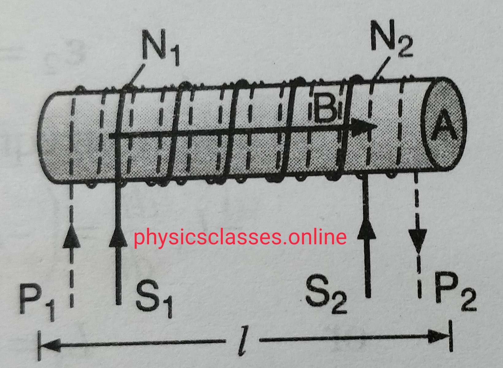
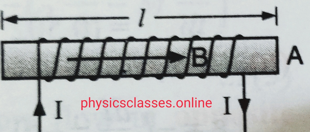
mutual induction fig.-
Let us consider two coaxial solenoid P1P2 and S1S2 (as shown in figure).
Let their common length is ‘l’ with cross-sectional area A and having N1 turns but second coil has N2 turns .
If I1 is the current flows through the coil P1P2 , the magnetic field at its centre , B = µ0 n1 I . so magnetic flux linked with the coil S1S2 = B A .
Magnetic flux for entire coil S1S2 , ɸ = BAN2 = µ0n1n2 A I = µ0 N1N2 I A/ l …………(i)
But as we know , ɸ= MI ……………….(ii) (Here M is the mutual induction of the coil)
From eq. (i) and (ii)
MI = µ0 N1N2 I A / l
So M= µ0 N1N2 A/l .
Points to be remember-
If a medium of relative permeability µr fills the entire space in the inner solenoid then mutual induction M= µ0µr N1N2 A/l
If the cross-sectional area of both the the coils are different then we always consider the inner coil radius ( area of that coil having smaller area of cross-section)
The calculation of mutual induction is quite complicated even in the case of considerable symmetry.
In this topic students will study what is mutual induction and coefficient of mutual induction / mutual inductance? And what is the unit of mutual inductance
mutual induction
Mutual induction-
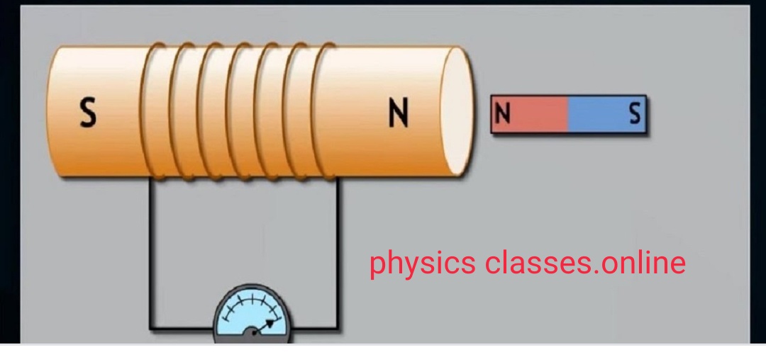
Let us consider two coils placed near to each other closely . One of the coil carries the battery is the primary coil and the other one is secondary coil connected with a galvanometer. When current starting flows through the primary coil then its value increases from zero value to a fixed value during this time we observe that there is some deflection in the galvanometer . as we know when current passes through a coil (solenoid ) magnetic field setup ,due to increasing value of current magnetic field through the coil also increases and hence magnetic flux linked with the secondary coil also increases , and according to Faraday’s law emf setup across the secondary coil .
So we can say , The phenomena of inducing current in a circuit by changing the current in a neighbouring circuit is called mutual induction. We can also define it the property of two circuits by virtue of which each circuit opposes any change in flux or strength of current flowing through other circuit.
It is found that the flux ‘ɸ’ linked with the secondary coil is directly proportional to the current ‘I’ flowing through the primary coil ,
i.e. ɸ = I
or ɸ = MI ( M is a constant called coefficient of mutual induction , the value of M depends upon the characteristics of the circuit ant their orientations . )
so, M = ɸ/I ; if I =1 ampere then M=ɸ
So we can define coefficient of mutual induction is equal to the flux linked with the coil when unit current passes through the another coil.
If dI/dt = 1 then , m = – e , so we can define coefficient of mutual induction is equal to emf induced in secondary coil when rate of change of secondary coil is unity.
Unit of mutual inductance is Henry (H) , Henry is also the unit of self inductance , we can define that mutual induction of two circuit is said to be 1 Henry if a current changing at the rate of 1 ampere per second in one circuit and induces 1 volt of emf in other circuit.
This topic only explain the term definition of Ampere ( which is explain in different-different type . Students can learn it according to there needs. )
Ampere is the basic unit of electric current . It is named after Andre-Marie -Ampere a French scientist born in 1775 . He also known as the father of electrodynamics .
Definition of Ampere– 1 Ampere is the current flowing through a conductor when 1 Coulomb of charge flows through a conductors in unit time.
From Ohm’s law – potential difference across the conductor is directly proportional to the current flowing through the conductor , if V is the potential difference across the conductor and I be the current flowing through the conductor then according to Ohm’s law V α I or V= RI , where R is the resistance of the conductor . ( resistance of a conductor is the property of the conductor to restrict the flow of current through it) i.e. current I =V/R,
So we can say, 1 Ampere current flows through a conductor when unit potential difference setup across a conductor of resistance 1 Ohm .
Another definition of current can be determined using the property of force between two parallel current carrying conductor according to it force between two parallel current carrying conductor can be given as force per unit length (f/l) F= µ0I1 I2 /2Πd ( Here I1 and I2 are the current through the wires and , d is the separation between them . according to given relation we can define, 1 Ampere is the electric current which when flowing in each of parallel conductors placed at separation 1 m in vacuum exert a force of 2x 10⁻⁷N on 1 meter length of either wire.
When electric charges is in motion , they constitute what is called an electric current . electric current is defined as the rate of flow of charge through an area of the conductor . if Q is the charge flows through a conductor in time T then electric current I = Q/T
Or I= dQ /dt . unit of current is Ampere .
We can define 1 Ampere is the current flowing through a conductor when 1 Coulomb of charge flows through a conductors in unit time.
In the terms of drift velocity current I = n e A Vd where n is the charge density , A is the area of cross-section of the conductor , e is the charge on electron and Vd is the drift velocity.
In terms of Ohm’s law – current I = V/R V is the potential difference across the conductor and R is the resistance of the conductor .
So we can say 1 Ampere current flows through a conductor when unit potential difference setup across a conductor of resistance 1 Ohm .
Ampere is the basic unit of electric current . It is named after Andre-Marie -Ampere a French scientist born in 1775 . He also known as the father of electrodynamics .
Definition of Ampere– 1 Ampere is the current flowing through a conductor when 1 Coulomb of charge flows through a conductors in unit time.
From Ohm’s law – potential difference across the conductor is directly proportional to the current flowing through the conductor , if V is the potential difference across the conductor and I be the current flowing through the conductor then according to Ohm’s law V α I or V= RI , where R is the resistance of the conductor . ( resistance of a conductor is the property of the conductor to restrict the flow of current through it) i.e. current I =V/R,
So we can say, 1 Ampere current flows through a conductor when unit potential difference setup across a conductor of resistance 1 Ohm .
Another definition of current can be determined using the property of force between two parallel current carrying conductor according to it force between two parallel current carrying conductor can be given as force per unit length (f/l) F= µ0I1 I2 /2Πd ( Here I1 and I2 are the current through the wires and , d is the separation between them . according to given relation we can define, 1 Ampere is the current which when flowing in each of parallel conductors placed at separation 1 m in vacuum exert a force of 2 x 10⁻⁷ N on 1 meter length of either wire.
Suppose a long air cored solenoid having ‘n’ number of turns per unit length . If current in the solenoid is ‘I’ the magnetic field within the solenoid B= µ0nI . If A is the area of cross-section of the solenoid , the effective flux linked with the solenoid of length ‘l’ ; ɸ=NBA……………………………….(i)
where N is the total no. of turns of the solenoid . so ɸ= n l B A …………………………………….(ii) . substituting the value of B in this equation
we get,
ɸ =n l(µ0nI ) A = µ0n2A l I .
so , self-inductance of solenoid L=ɸ/ I.= µ0n2A l I / I = µ0 n2 Al
but n= N/l
so self- inductance L= µ0 N2A/ l .
If solenoid contains a core of ferromagnetic material , having relative permeability µr then self-inductance L= µ0µr N2A/ l .
It is the property of an electric circuit or coil by virtue of which it opposes any change of flux or current in it by inducing a current in itself is called self- induction. In another words we can say “self-induction is the inertia of electricity “. Due to self -induction an electric circuit resist any change of current through it .
As we know magnetic flux linked with a coil is directly proportional to the current flowing through the circuit
i.e. ɸ α I ( ɸ= flux linked with the coil, and I is the current in the circuit )
ɸ = LI ( L is the constant called coefficient of self- induction or self-inductance or only inductance . )
If current I = 1 ampere, then flux ɸ= L . so we can define self-induction is the flux linked with the coil when unit current passes through the coil.
as we know,
emf e= – dɸ/dt
e= -d (LI)/ dt
e= -L ( dI/dt)
L= – e/(dI/dt)
So we can define self-inductance of a circuit is numerically equal to the induced emf setup in it when the rate of change of current through it is unity.
Unit of self-inductance is Henry (H) . We can define self-inductance of a coil is one Henry if 1 volt emf induced in the coil when rate of change of current through the coil is unity.
What is electric current ? what is its unit ? define Ampere.
Electric current-When electric charges is in motion , they constitute what is called an electric current . electric current is defined as the rate of flow of charge through an area of the conductor . if Q is the charge flows through a conductor in time T then electric current I = Q/T
Or I= dQ /dt . unit of current is Ampere .
We can define 1 Ampere is the current flowing through a conductor when 1 Coulomb of charge flows through a conductors in unit time.
In the terms of drift velocity current I = n e A Vd where n is the charge density , A is the area of cross-section of the conductor , e is the charge on electron and Vd is the drift velocity.
Subscribe to Video Tutorial ( Nayan Jha Sir )
In terms of Ohm’s law – current I = V/R V is the potential difference across the conductor and R is the resistance of the conductor .
So we can say 1 Ampere current flows through a conductor when unit potential difference setup across a conductor of resistance 1 Ohm .
Electromagnetic induction – As we know when electric current passes through a conductor then magnetic field developed across the conductor , first discovered by Oersted . But Michael Faraday found its converse is also possible i.e. Whenever magnetic field changes around a coil ( and hence magnetic flux linked across the coil changes ) electric current induced in the coil , such phenomena is called electromagnetic induction (E.M.I.) . And the current induced in the coil is known as induced current and emf developed is known as induced emf .
Faraday’s law of EMI
Faraday’s laws of electromagnetic induction – On the basis of experiments Faraday’s gave the two laws –
(i) Whenever electric flux linked with the coil changes then emf induced in the coil . The emf lasts only for the time for which flux is changing .
(ii) The magnitude of induced emf is directly proportional to rate of change of magnetic flux linked with the coil. I.e. emf e α ɸ2 – ɸ1 / t (time taken).
Or e = – k dɸ/ dt . ( Here negative sign shows the induced emf oppose any change in the magnetic flux through the coil.
After combining these two equations Faraday’s law states “ An induced emf is produced in any closed circuit if there is a varying magnetic flux . the magnitude of induced emf is equal to the negative of the time rate change of magnetic flux through the circuit .”