– Parallax method has been used for measuring distance of stars which are less than 100 light years away.(parallax is the name given to change in the position of an object with respect to the back ground , when the object is seen from the two different positions .)
PARALLAX METHOD FIGURE
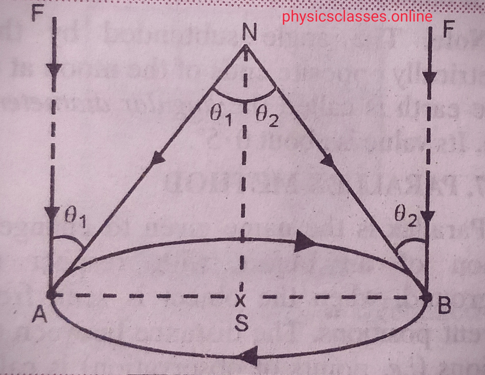
The diameter AB of earth’s orbit around the sun is chosen as the base line as shown in the fig. . N is the nearby star whose distance (d) from the earth is to be measured . F is a far off star whose direction is taken practically the same at all position of earth in its orbital motion .
Suppose A is the position of earth in its orbital motion at any time . using an astronomical telescope we measure <FAN = θ1 , between the directions of light from distant star F and nearby star N . As it clear from the figure <FAN = <ANS =θ1 .
After six months earth is at B which is directly opposite to the point A , let < FBN =θ2, between the direction of light from distant star F and nearby star N is measured again <FBN = <BNS = θ2
Clearly , <ANB = <ANS +<BNS = θ1 + θ2 .
As we know , angle = arc/ radius
Therefore , θ1 + θ2 = AB/AN
Or AN = AB / θ1 + θ2 .
Clearly AB= 2AS = 2AU
If θ1 and θ2 is known then AN can be calculated.
( Note – the parallax method is used for measuring distance of nearby stars only. And parallax method is also used for determining distance of moon from earth ).
This topic only explain the term definition of Ampere ( which is explain in different-different type . Students can learn it according to there needs. )
Ampere is the basic unit of electric current . It is named after Andre-Marie -Ampere a French scientist born in 1775 . He also known as the father of electrodynamics .
Definition of Ampere– 1 Ampere is the current flowing through a conductor when 1 Coulomb of charge flows through a conductors in unit time.
From Ohm’s law – potential difference across the conductor is directly proportional to the current flowing through the conductor , if V is the potential difference across the conductor and I be the current flowing through the conductor then according to Ohm’s law V α I or V= RI , where R is the resistance of the conductor . ( resistance of a conductor is the property of the conductor to restrict the flow of current through it) i.e. current I =V/R,
So we can say, 1 Ampere current flows through a conductor when unit potential difference setup across a conductor of resistance 1 Ohm .
Another definition of current can be determined using the property of force between two parallel current carrying conductor according to it force between two parallel current carrying conductor can be given as force per unit length (f/l) F= µ0I1 I2 /2Πd ( Here I1 and I2 are the current through the wires and , d is the separation between them . according to given relation we can define, 1 Ampere is the electric current which when flowing in each of parallel conductors placed at separation 1 m in vacuum exert a force of 2x 10⁻⁷N on 1 meter length of either wire.
When electric charges is in motion , they constitute what is called an electric current . electric current is defined as the rate of flow of charge through an area of the conductor . if Q is the charge flows through a conductor in time T then electric current I = Q/T
Or I= dQ /dt . unit of current is Ampere .
We can define 1 Ampere is the current flowing through a conductor when 1 Coulomb of charge flows through a conductors in unit time.
In the terms of drift velocity current I = n e A Vd where n is the charge density , A is the area of cross-section of the conductor , e is the charge on electron and Vd is the drift velocity.
In terms of Ohm’s law – current I = V/R V is the potential difference across the conductor and R is the resistance of the conductor .
So we can say 1 Ampere current flows through a conductor when unit potential difference setup across a conductor of resistance 1 Ohm .
Ampere is the basic unit of electric current . It is named after Andre-Marie -Ampere a French scientist born in 1775 . He also known as the father of electrodynamics .
Definition of Ampere– 1 Ampere is the current flowing through a conductor when 1 Coulomb of charge flows through a conductors in unit time.
From Ohm’s law – potential difference across the conductor is directly proportional to the current flowing through the conductor , if V is the potential difference across the conductor and I be the current flowing through the conductor then according to Ohm’s law V α I or V= RI , where R is the resistance of the conductor . ( resistance of a conductor is the property of the conductor to restrict the flow of current through it) i.e. current I =V/R,
So we can say, 1 Ampere current flows through a conductor when unit potential difference setup across a conductor of resistance 1 Ohm .
Another definition of current can be determined using the property of force between two parallel current carrying conductor according to it force between two parallel current carrying conductor can be given as force per unit length (f/l) F= µ0I1 I2 /2Πd ( Here I1 and I2 are the current through the wires and , d is the separation between them . according to given relation we can define, 1 Ampere is the current which when flowing in each of parallel conductors placed at separation 1 m in vacuum exert a force of 2 x 10⁻⁷ N on 1 meter length of either wire.
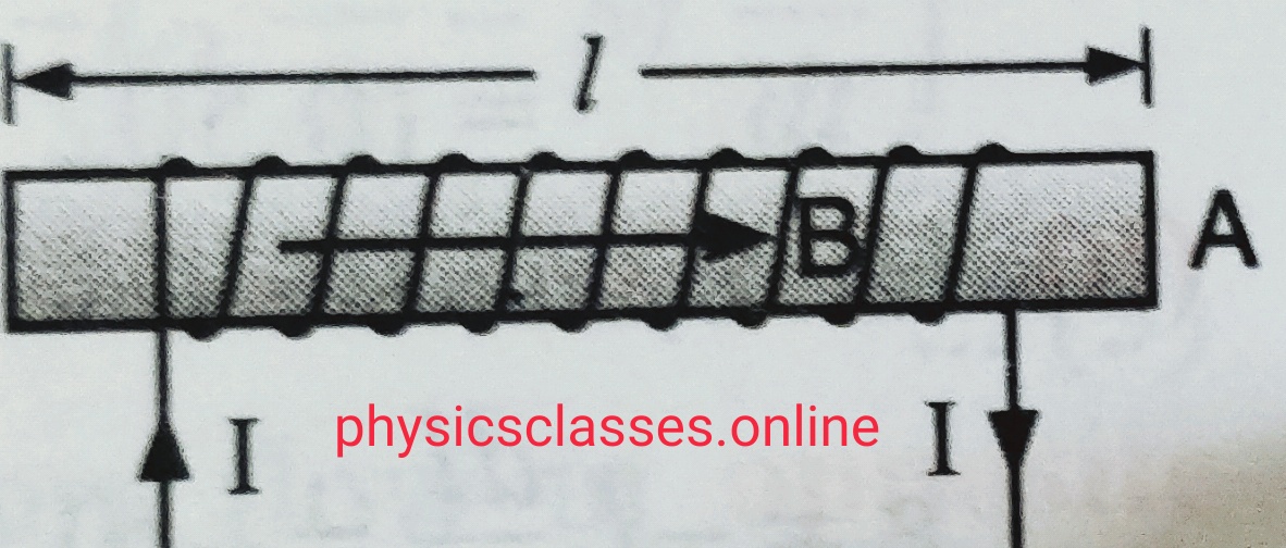
Suppose a long air cored solenoid having ‘n’ number of turns per unit length . If current in the solenoid is ‘I’ the magnetic field within the solenoid B= µ0nI . If A is the area of cross-section of the solenoid , the effective flux linked with the solenoid of length ‘l’ ; ɸ=NBA……………………………….(i)
where N is the total no. of turns of the solenoid . so ɸ= n l B A …………………………………….(ii) . substituting the value of B in this equation
we get,
ɸ =n l(µ0nI ) A = µ0n2A l I .
so , self-inductance of solenoid L=ɸ/ I.= µ0n2A l I / I = µ0 n2 Al
but n= N/l
so self- inductance L= µ0 N2A/ l .
If solenoid contains a core of ferromagnetic material , having relative permeability µr then self-inductance L= µ0µr N2A/ l .
It is the property of an electric circuit or coil by virtue of which it opposes any change of flux or current in it by inducing a current in itself is called self- induction. In another words we can say “self-induction is the inertia of electricity “. Due to self -induction an electric circuit resist any change of current through it .
As we know magnetic flux linked with a coil is directly proportional to the current flowing through the circuit
i.e. ɸ α I ( ɸ= flux linked with the coil, and I is the current in the circuit )
ɸ = LI ( L is the constant called coefficient of self- induction or self-inductance or only inductance . )
If current I = 1 ampere, then flux ɸ= L . so we can define self-induction is the flux linked with the coil when unit current passes through the coil.
as we know,
emf e= – dɸ/dt
e= -d (LI)/ dt
e= -L ( dI/dt)
L= – e/(dI/dt)
So we can define self-inductance of a circuit is numerically equal to the induced emf setup in it when the rate of change of current through it is unity.
Unit of self-inductance is Henry (H) . We can define self-inductance of a coil is one Henry if 1 volt emf induced in the coil when rate of change of current through the coil is unity.
What is electric current ? what is its unit ? define Ampere.
Electric current-When electric charges is in motion , they constitute what is called an electric current . electric current is defined as the rate of flow of charge through an area of the conductor . if Q is the charge flows through a conductor in time T then electric current I = Q/T
Or I= dQ /dt . unit of current is Ampere .
We can define 1 Ampere is the current flowing through a conductor when 1 Coulomb of charge flows through a conductors in unit time.
In the terms of drift velocity current I = n e A Vd where n is the charge density , A is the area of cross-section of the conductor , e is the charge on electron and Vd is the drift velocity.
Subscribe to Video Tutorial ( Nayan Jha Sir )
In terms of Ohm’s law – current I = V/R V is the potential difference across the conductor and R is the resistance of the conductor .
So we can say 1 Ampere current flows through a conductor when unit potential difference setup across a conductor of resistance 1 Ohm .
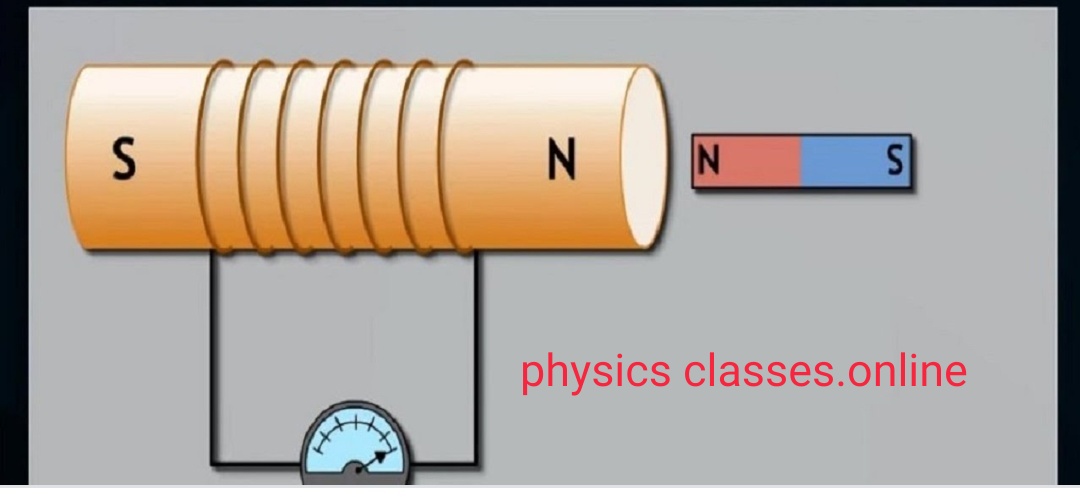
Electromagnetic induction – As we know when electric current passes through a conductor then magnetic field developed across the conductor , first discovered by Oersted . But Michael Faraday found its converse is also possible i.e. Whenever magnetic field changes around a coil ( and hence magnetic flux linked across the coil changes ) electric current induced in the coil , such phenomena is called electromagnetic induction (E.M.I.) . And the current induced in the coil is known as induced current and emf developed is known as induced emf .
Faraday’s law of EMI
Faraday’s laws of electromagnetic induction – On the basis of experiments Faraday’s gave the two laws –
(i) Whenever electric flux linked with the coil changes then emf induced in the coil . The emf lasts only for the time for which flux is changing .
(ii) The magnitude of induced emf is directly proportional to rate of change of magnetic flux linked with the coil. I.e. emf e α ɸ2 – ɸ1 / t (time taken).
Or e = – k dɸ/ dt . ( Here negative sign shows the induced emf oppose any change in the magnetic flux through the coil.
After combining these two equations Faraday’s law states “ An induced emf is produced in any closed circuit if there is a varying magnetic flux . the magnitude of induced emf is equal to the negative of the time rate change of magnetic flux through the circuit .”
Assignment for short answer type questions of electromagnetic induction and alternating current
this Assignment for short answer type questions of electromagnetic induction and alternating current contain all short type questions which is important for board examination of class 12th
SHORT ANSWER TYPE QUESTIONS.
Q1. In a series LCR circuit, obtain the conditions under which (i)the impedance of the circuit is minimum and (ii)wattles current flows in the circuit.
Q2. what is the power dissipated by an ideal inductor in AC circuit? Explain.
Q3. When an AC source is connected to an ideal capacitor, show that the average power supplied by the source over a complete cycle is zero.
Q4. Prove that the power dissipated in an ideal resistor connected to an AC source is Veff2 / R.
Q5. State the principle of working of a transformer. Can a transformer be used to step up or step down a d.c. voltage ? Justify your answer.
Q6. State the underlying principle of a transformer. How is the large scale transmission of electric energy over long distances done with the use of transformers?
Q7. Define power factor. State the conditions under which it is (i)maximum (ii) minimum.
Q8. Show that the current leads the voltage in phase by n/2 in an AC circuit containing an ideal capacitor.
Q9. State Lenz’s law.
A metallic rod held horizontally along east- west direction, is allowed to fall under gravity. Will there be an emf induced at its ends? Justify your answer.
Q10. show that Lenz’s law is in accordance with the law of conservation of energy.
Q11. In an experimental arrangement of two coils C1 and C2 placed coaxially parallel to each other, find out the expression for the emf induced in the coil C1 (of N1 turns) corresponding to the change of current I2 in the coil C2 (of N2 turns).
Q12. (a)How does the mutual inductance of a pair of coils change when
(i)distance between the coils increased and
(ii)number of turns in the coil increased
(b) A plot of magnetic flux (ɸ) versus current (I), is shown in the figure for two inductors A and B. which one the two has large value of self inductance?
(c)How is the mutual inductance of a pair of coils effected when
(i)separation between the coils increased
(ii)the number of turns in each coil is increased
(iii)a thin iron sheet is placed between the two coils, other factors remaining the same ?
Q13. Define self-inductance of a coil . show that magnetic energy required to build up the current I in a coil of a self inductance L. is given by½ LI2. .
OR
Define the term self- inductance of a solenoid. Obtain the expression for the magnetic energy stored in an inductor of self- inductance L. to build up a current I through it.
TO DOWNLOAD/READ LONG ANSWER TYPE QUESTIONS CLICK HERE
Assignment of electromagnetic induction and alternating current
This assignment of electromagnetic induction and alternating current contain long answer type questions ( derivation and reasoning type questions. )
electromagnetic induction
LONG ANSWER TYPE QUESTIONS OF ELECTROMAGNETIC INDUCTION AND ALTERNATING CURRENT
Q1. Explain with the help of a labelled diagram, the principle and working of an ac generator. Write the expression for the emf generated in the coil in terms of speed and rotation. Can the current produced by an ac generator be measured with a moving coil galvanometer ?
OR
Describe briefly , with the help of a labelled diagram, the basic elements of an ac generator. State its underlying principle. Show diagrammatically how an alternating emf is generated by a loop of wire rotating in a magnetic field. Write the expression for the instantaneous value of the emf induced in the rotating loop.
OR
State the working of ac generator with the help of a labelled diagram . the coil of an ac generator having N turns, each of area A, is rotated with a constant angular velocity ω. Deduce the expression for the alternating emf generated in the coil. What is the source of energy generation in this device?
Q2. derive an expression for impedance of an a.c. circuit consisting of an inductor and a resistor.
Q3. (a)State the condition for resonance to occur in series LCR a.c. circuit and derive an expression for resonant frequency.
(b) Draw a plot showing the variation of the peak current (im)with frequency of the a.c. source used. Define the quality factor Q of the circuit.
Q4. Define the term capacitive reactance. Show graphically the variation of capacitive reactance with frequency of applied alternating voltage.
An ac voltage V=V0 sin ωt is applied across a pure capacitor of capacitance C. Find an expression for current flowing through it. Show mathematically the current flowing through it leads the applied voltage by angle π/2.
Q5. Explain the term inductive reactance. Show graphically the variation of inductive reactance with frequency of the applied alternating voltage.
An ac voltage V=V0 sin ωt is applied across a pure inductor of inductance L. Find an expression for current i, flowing in the circuit . Show mathematically the current flowing through it lags behind the applied voltage by phase angle π/2. Also draw (i) phasor diagram (ii) graphs of V an I versus ωt for the circuit.
Q6. Derive an expression for (i)induced current when a conductor of length l is moved with a uniform velocity v. normal to a uniform magnetic field B. Assume the resistance of conductor to be R.
Q7. (a)What is induced emf ? write Faraday’s law of electromagnetic induction. Express it Mathematically.
(b) A conducting rod of length l with one end pivoted, is rotated with a uniform angular speed ω in a vertical plane, normal to a uniform magnetic field B. deduce an expression for the emf induced in this rod.
If resistance of rod is R, what is the current induced in it.
Q8. A coil of number of turns N, Area A is rotated at a constant angular speed ω in a uniform magnetic field B and conducted to a resistor R. Deduce the expression for
(i)Maximum emf induced in the coil.
(ii) Power dissipation in the coil .
Q9. (a)Describe briefly, with the help of a labeled diagram, the working of a step up transformer.
(b) Write any two source of energy loss in a transformer.
(c) A set up Transformer converts a low voltage into high voltage. Does it not violate the principle of conservation of energy? Explain.
OR
Draw a schematic Diagram of a set up transformer. Explain its working principle . Deduce the expression for the secondary to primary voltage in turms of number of turns in the two coils. In an ideal transformer, how is this ratio related to the current in the two coils?
How is the transformer used in large scale transmission and distribution of electrical energy over long distances?
Q10. An ac source of voltage V=Vm sin ωt is connected one by one, to three circuit elements X,Y and Z. It is observed that the current flowing in them.
(a) is in the phase with applied voltage for element X.
(b) lags the applied voltage, in phase, by angle π/2 for element Y.
(c) leads the applied voltage in phase by angle π/2.
Identify the three circuit elements.
Find an expression for for the current flowing in the circuit, when the same ac source is connected across a series combination of the elements X,Y and Z.
If the frequency of the applied voltage is varied, set up the condition of the frequency when the current amplitude in the circuit is maximum. Write expression for this current amplitude.
Q11. (a)What is impedance?
(b) A series LCR circuit is connected to an ac source having voltage V=V0 sin ωt. Derive an expression for the impedance, instantaneous current and its phase relationship to the applied voltage. Find the expression for the resonant frequency
OR
(a) ac source having voltage V=V0 sin ωt is connected to a series combination of L, C and R. Use the phasor diagram to obtain expression for impedance of the circuit and phase angle between voltage and current. Find the condition when the current will be in phase with the voltage. What is the circuit in this condition called?
(b)In a series LR circuit XL = R and power factor of the circuit is P1. When capacitor with capacitance C such that XL=XC is put in series, the power factor becomes P2 calculate P1/P2 .
Q12. Derive Expression for self inductance of a long air- cored solenoid of length l, cross- sectional area A and having number of turns N.
Q13. What do mean by mutual inductance of two nearby coils ? Find an expression for mutual inductance of two co-axial solenoid.
OR
(a)Define mutual inductance and write its SI units.
(b)Derive an expression for the mutual inductance of two long co – axial solenoid of same length wound one over the other.
(c)In an experiment, two coils C1 an C2 are placed close to each other. Find out the expression for the emf induced in the coil C1 due to change in the current through coil C2.