Category: 12th Notes

  • Non-polar and polar dielectrics

    Non-polar and polar dielectrics

    Non-polar and polar dielectrics –

    In this topic we will discuss about Non-polar and polar dielectrics and dielectric polarization with electrical susceptibility.

    Non polar and polar dielectrics  –

    As we know the dielectrics are insulating material which transmit electric effect without conducting electricity .

    Dielectrics is of two types , Non-polar Dielectrics and polar Dielectrics .

    In non-polar dielectric ,  in the molecule of the dielectric the centre of mass of the positive charge coincide with the centre of mass of the negative charge . Like , Hydrogen , nitrogen , oxygen , carbon dioxide , methane , benzene etc . In such kind of molecule each molecule has zero dipole moment and they are symmetric in shape .

    But in case of polar dielectric . The  centre of mass of positive and negative charges do not coincide  because of the asymmetric shape of the molecules. It has permanent dipole moment . example – HCl , NH3 H2O, alcohol etc .

    Dielectric polarization –

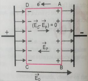
    When a non polar dielectric is held in external electric field , the two centres of positive and negative charges in the molecules are separated . The molecules gets distorted and is said to be polarized as a small dipole moment .

    The dipole moment acquired is given as , p = αϵ0E0  Where α is the constant of proportionality called molecular polarizability .  Its unit is m3 .

    If N is the number of atoms per unit volume then , electric polarization P = N p   or,  P = N qx .

    Its unit is C-m-2
    If we consider a small volume element in the interior of the slab  as shown in figure . , each volume has no net charge ,though it has net dipole moment . This is because positive charge of each dipole sits close to the negative charge of the adjacent dipole . . The negative end of the dipole remain un-neutralized  at the surface AB and positive end of the dipole at CD . then the effective electric field E = E0 -EP  ;

    Further EP = σ/ϵ =  p/ϵ.

    Electric susceptibility –  As we know that the electric polarization P αE    or, p= ϵ  χ E

    Where  χ is constant called electrical susceptibility .

    For vacuum χ = 0 ;

    But as we know ,   E = E0 -EP  = E0 – P/ϵ = E0  –  ϵ  χ E/ϵ

    Or , E = E0 -χE  ;

    E0 = E  +   χ E  = E( 1+ χ )

    OR ,             E0/E  =  1 + χ

    K ( Dielectric constant or relative permittivity ) = 1 + χ   [ since  K= E0/E  ]

    K (ϵr) = 1 +  χ …………………This is the relation between relative permittivity and susceptibility .
  • Common potential and loss in energy on shearing charges .

    Common potential and loss in energy on shearing charges .

    Common potential and loss in energy on shearing charges .

    Before to know about the topic Common potential and loss in energy on shearing charges .student must have to know about Energy stored in the capacitor and electrostatic potential .

    To know about energy stored in a capacitor click here-

    To know about the electrostatic potential energy click here- 

    In this topic students will know about Common potential and loss in energy on shearing charges . its derivation and numerical is important for class 12th ( Board examination) and for NEET/JEE examinations .

    Common potential – When two charged capacitors are connected with each other using a conducting wire then charge starts flowing from high potential to low potential, and after some time their potential becomes equal.

    Let two capacitors C1 and C2 and their potentials are V1 And V2 respectively. Then total charge before combination Q = C1V1 + C2V2.

    Let they are connected with a conducting wire, then charge start flowing from high potential to low potential, till potential is not equal. Let V is the common potential then total charge after combination Q = V (C1 + C2).

    But from the conservation of energy charge after collision = charge before collision

    So, C1V1 + C2V2 = (C1 + C2) V

    Then     V = C1V1 + C2V2 / (C1 + C2)………………………eq.


    Loss of energy on shearing charges –

    As we have seen in the above equation  common potential after combination

    V = C1V1 + C2V2 / (C1 + C2)

    Total energy before combination U1 = ½ C1V12 + ½ C2V22

    Total energy after combination  U2= ½ ( C1 + C2 ) V2 ; Putting the value of  V

    We get , U2= ½ ( C1 + C2 ) [C1V1 + C2V2 / (C1 + C2)]2

    = ( C1V1+C2V2 )2 /2(C1+C2 )

    Then loss in energy ;

    =U1-U2 = [½ C1V12 + ½ C2V22] – [( C1V1+C2V2 )2 /2(C1+C2 )]

    = [C1V12(C1+C2 )+C2V22 (C1+C2 )- (C1V1+C2V2)2]/2(C1+C2) ;

    = C1C2(V12+V22-2V1V2)/2(C1+C2) Or  U1-U2 = C1C2(V1-V2)2/2(C1+C2) . Which is positive for all  possible values of  C1 , C2 And V1 , V2 .

    I.e .  U1 – U2 >0 ( POSITIVE ) .

    So, U1 > U2 . Therefore we can say that there is always loss in energy during the combination of charged capacitors .


  • Energy stored in a capacitor and energy density

    Energy stored in a capacitor and energy density

    Energy stored in a capacitor and energy density .

    Before to know about the Energy stored in a capacitor and energy density , student must have to know about capacitors . To know about the capacitor click here–

    In this topic we will discuss about the Energy stored in a capacitor and energy density, when a capacitor is charged from zero to Q .

    ENERGY STORED IN A CAPACITOR –

    Suppose the plates of the capacitor is initially uncharged , and the charge is to be transferred from plate 2 to plate 1 , at a small time charge dQ transferred and at the final time it reaches from 0 to Q .   


    Let V is the potential difference across the plates then work done for small instant is

    dW = V . dQ  = (Q/C)dQ .

    integrating both sides,

    ∫ dW =∫(Q/C)dQ from limit 0 to Q ,  then we get ,

    net work done W = Q2/2C ,

    also as we know Q=CV,  so work done may be written as ,

    W = potential energy stored = U =( ½) CV2   = ½ QV .

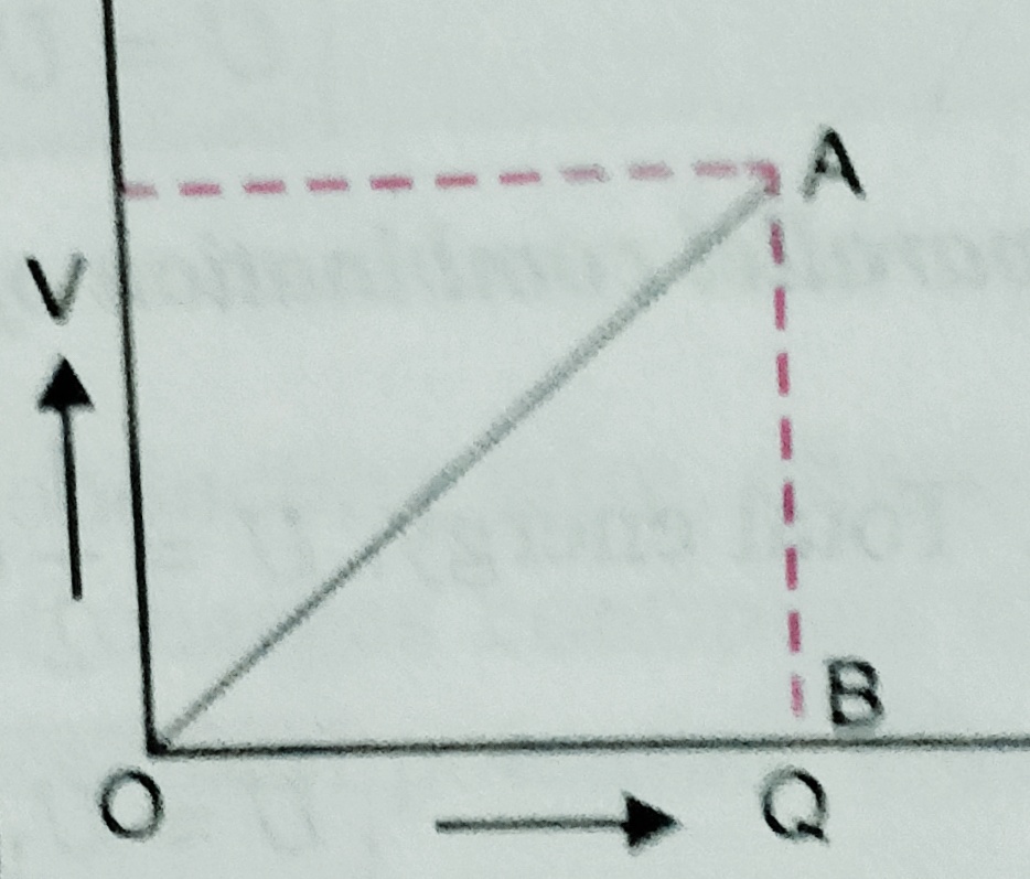
    If we plot the graph  potential v/s charge we get,


    ***Similarly we can plot the graph (i)  U v/s V ( when C is constant )

    (ii) U v/s C (when V is constant)

    (iii) U v/s V  (when Q is constant)

    Total energy stored in the combination of capacitors –

    In  series combination –  U = Q2/2CS But in series combination 1/Cs = 1/C1  + 1/C2 + 1/C3   ….

    So we can write in series combination total energy U = U1 + U2 + U3 + …..

    In parallel combination – U = ½ Cp V2 = ½ C1 V2 + ½ C2 V2 + ½ C3V2 …..

    So we can write in parallel combination total energy of the combination   U = U1+ U2 + U3 ……

    Energy density of a  parallel plate capacitor –

    Energy density of the capacitor is the energy stored per unit volume of the capacitors or condensers . We can write energy density u = U/ ( volume )

    u = ( ½ C V2 )/ A d  ( Where A is the area of the plate and D is the separation between the plates .

    But potential V = E( electric field) d  . putting this value in the above equation we get  ,

    u = ½ ( ϵ0 A /d ) ( E2 d2 / Ad ) = ½ ϵ0 E2 .

    the  unit of energy density is  J/m3 .


  • Grouping of capacitors

    Grouping of capacitors

    Grouping of capacitors

    Before to know about grouping of capacitors students should know about parallel plate capacitor .To read about the topic parallel plate capacitor click here-

    This is the topic in which students will learn about grouping of capacitors , which contain series combination and parallel combination of the capacitors .

    (Combination) Grouping of capacitors or condensers  –

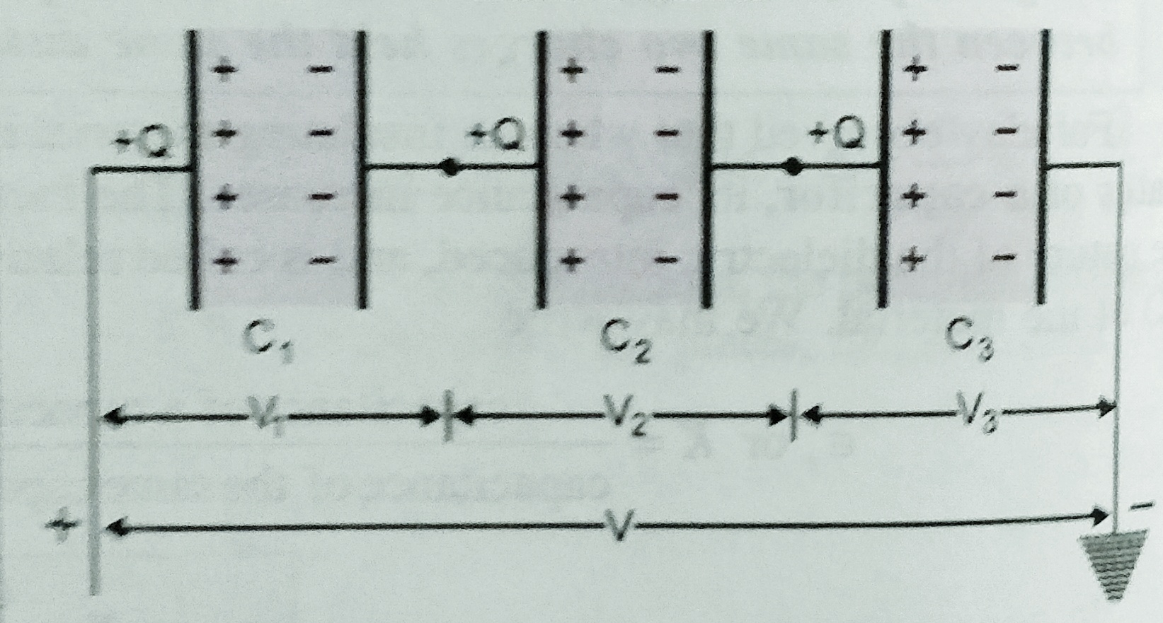
    1. Capacitors in series –   When negative plate of first capacitor is connected with positive of second , negative of second connected to positive of third and so on such combination is called series combination . in another words we can say that, the capacitors are said to be connected in series between two points , when we can proceed from one point to the other only through one path .

    As shown in figure three condensers of capacitance C1 , C2 and  C3  are connected in series .

    Suppose V is the potential difference across the combination .  Suppose   ‘Q’ charge is given to the left plate of C1 due to induction -Q charge setup on the other plates and =Q on the left plate of capacitor C2 and so on . Let V1, V2 and V3 are the potential difference setup across the capacitors  C1 , C2 and  C3  respectively . charge across the capacitors are same which is Q . Then V1 = Q/C1 , V2 = Q/C2 . V3 = Q/C3 . So net potential   V = V1 + V2 + V3 ;

    If CS is the equivalent capacitance of the combination of the capacitors then  ,

    Q/CS = Q/C1 +  Q/C2 + Q/C3

    Or ,  1/CS = 1/C1+ 1/C2 + 1/C3

    If there are n  capacitors are connected in series then

     1/CS = 1/C1+ 1/C2 + 1/C3 …………………+ 1/Cn


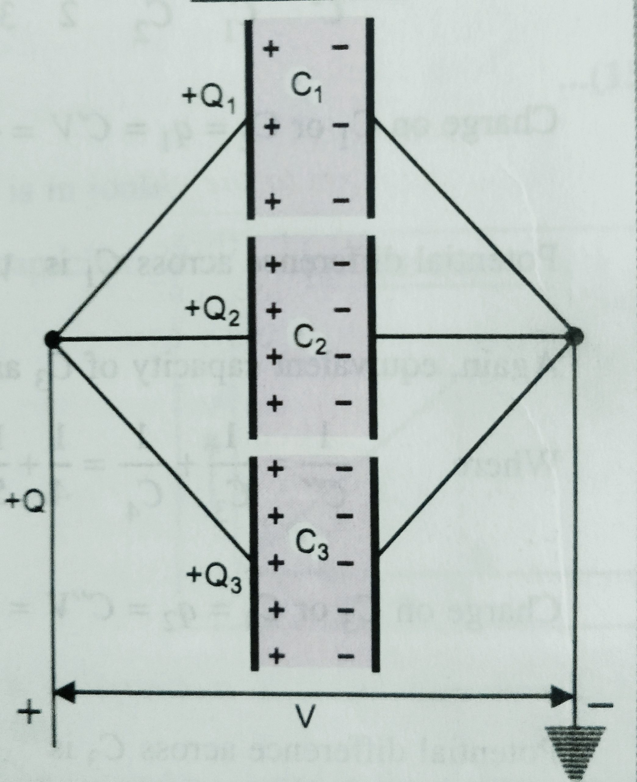
    1. Capacitors in parallel – The combination of the two or more capacitors are said to be in parallel if positive plates of capacitors are connected at one point and all negative plates at another points as shown in figure .

    Let C1 ,C2 , and C 3 are the capacitance of the three capacitors , and V is the potential difference applied across the combination . The potential difference across each capacitor is V the charge on each are Q1 Q2 and  Q3 , because their capacitance are different .  S o net charge Q = Q1 + Q2 + Q 3

    If CP is the equivalent capacitance of the capacitors then CP V =  C1 V + C2 V + C3 V

    So, Equivalent capacitance  CP  =  C1  + C2  + C3 ;

    If there are n  capacitors are connected in parallel then

    CP  =  C1  + C2  + C3……………..+ Cn


  • Parallel plate capacitor

    Parallel plate capacitor

    Parallel plate capacitor

    Before to know about these topics student must know about Electrical capacitance, To know about electrical capacitance click here-

    In this topic we will discuss about capacitance and its principle ,and expression for the capacitance of parallel plate capacitor .

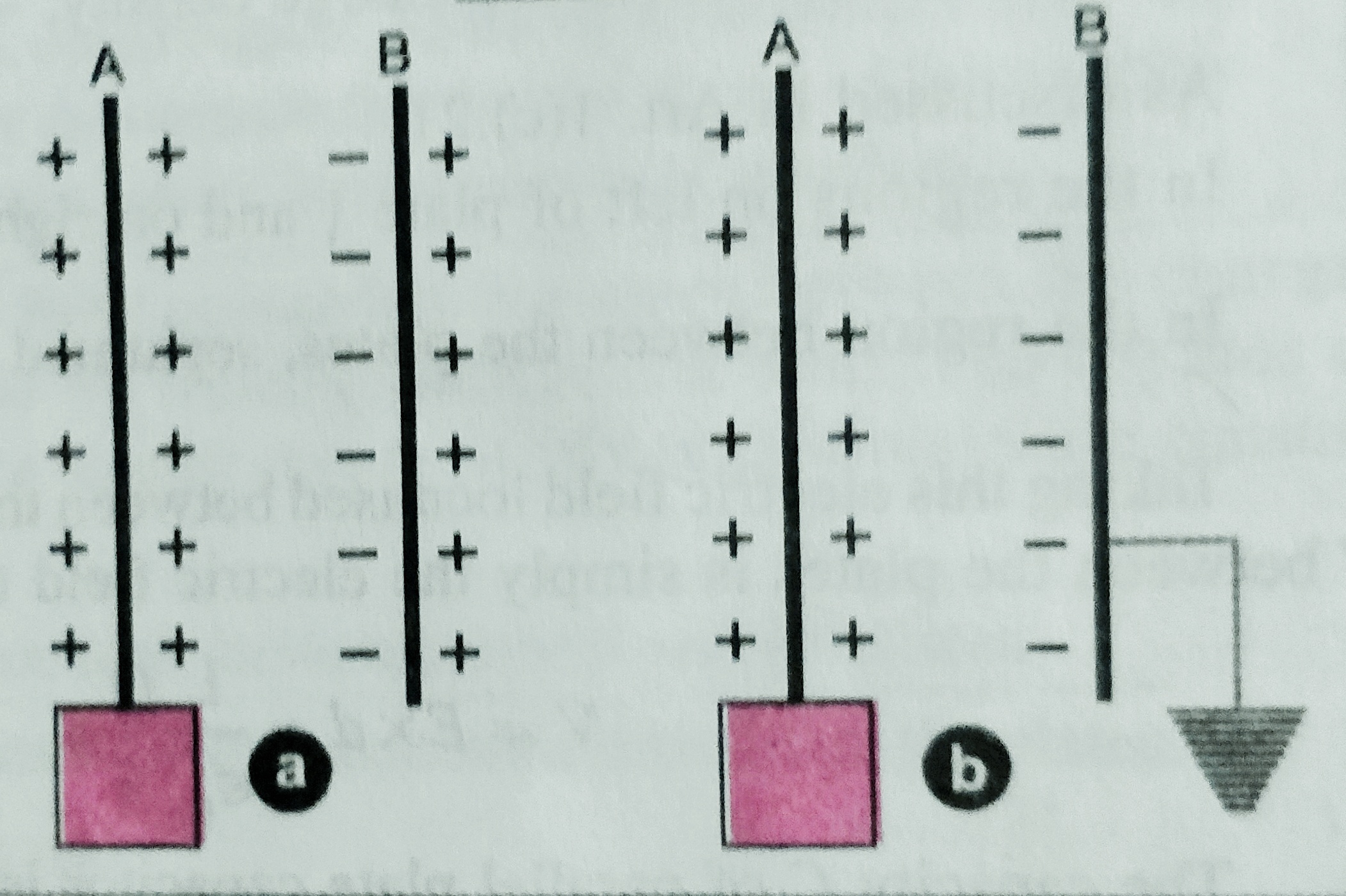
    Capacitor and its principle – It is an arrangement in which large amount of  electric charge can be stored and hence develop large potential difference in small space. A capacitor consists of a system of two conductors separated by an insulating medium. Often the two conductors are charged by connecting them to the two terminals of a battery.  Or we can say that the capacitance of an insulated conductor is increased considerably by bringing near it an uncharged conductor connected to earth.

     If the conductors are plane , the capacitor is called a parallel plate capacitor , when the conductor is spherical called spherical conductor , and if the conductor is cylindrical then the capacitor is called cylindrical capacitor .

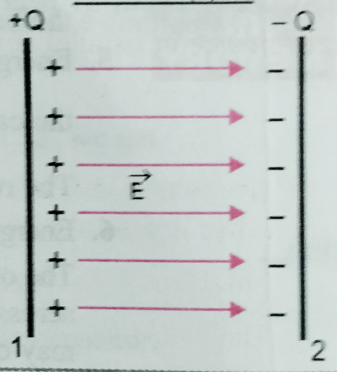
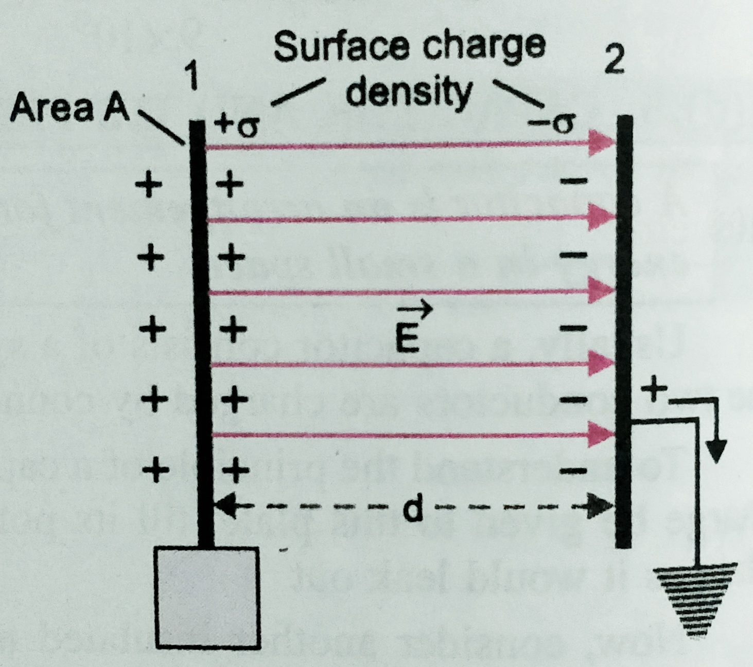
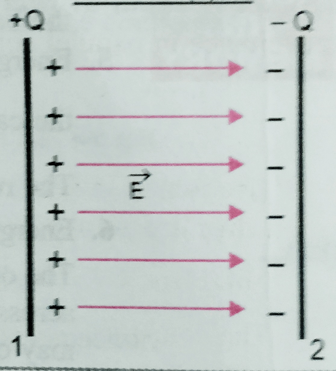
    Parallel plate capacitor – A parallel plate capacitor consists of two thin conducting plates each of plate area ‘A’  and separated by distance ‘d’ . One of the plate is insulated and the other plate is earthed .  When charge Q is given to one plate then the charge -Q is induced on the near face of the  second plate and +Q on the farther  face of the second plate , and +Q is flows to the earth .

    The surface charge density of the first plate is     +σ = Q/A

    And on the other plate is        -σ = -Q/A .

    So electric field between the plates is  E = σ/ϵ0 = Q/Aϵ0 ;

    Potential difference between the plates is V = E.d = Qd/Aϵ0 

    Hence capacity of the  capacitance will be C = Q/V = Q/( Qd/Aϵ0 ) = Aϵ0  / d   i.e . the capacitance of parallel plate capacitor is independent of the charge and potential .


  • Electrical capacitance

    Electrical capacitance

    Electrical capacitance

    In this topic we will discuss about the Electrical capacitance and electrostatics of conductor,electrostatic shielding  , and the capacity of an isolated spherical conductor .

    Electrostatics of conductor –

    As we know a conductor is a substance through which electric charge can conduct from one point to another . But there is some important results regarding  electrostatics of conductor which are follows –

    1. In electrostatic equilibrium , electric field is zero every where inside the conductor . Suppose a conductor ABCD is held in an external electric field of intensity E0 as shown in figure , the free electrons in the conductor moves from AB to CD . As a result , some net negative charge appears on AB . and the produced electric field Ep , which opposes the flow of free electrons from AB to CD . since Ep = E0 so net field inside the conductor is zero .

    1. The electric field just outside the charged conductor is perpendicular to the surface of the conductor at every point .
    2. Net charge in the interior of the conductor is zero .

    According to Gauss’s law  ∫E.ds =q/ϵ0 ];

    since inside the conductor E=0

    therefore q= 0 also ;

    1. Electric field at the surface of the charged conductor is given as E = σ/ϵ0 where σ is the surface charge density . and the surface charge density is different at different point for irregular shaped conductor .

    ELECTROSTATIC SHIELDING –

     It is the phenomenon to protect a space or an object from external electric field by covering it by conducting substance . as we know electric field inside a conductor is zero hence when an object is placed inside the conductor then there is no electric field connected to the object which is inside the conductor .

    Electrical capacitance –

    Electrical capacitance of a conductor is the ability of the conductor to store electric charge in it.

    When conductor given some charge then its potential increases . Let Q is the charge given to the conductor then its potential increases to V volt so , we can say,   Q α V  or , Q = CV ; where C is a constant called capacity of the conductor , we can write  capacity C = Q/V  , Using this expression we can write , capacity of a conductor is the ratio of charge given to the potential developed in the conductor i.e. C = Q/V ;


    In another way we can define , electrical capacity of a conductor is numerically equal to the charge required to increase the potential by unit volt .      Its unit is farad (F)

    Here 1 Farad =1 coulomb/1 volt and its dimension is [ M-1L-2T4A2]

    CAPACITY OF AN ISOLATED SPHERICAL CONDUCTOR –

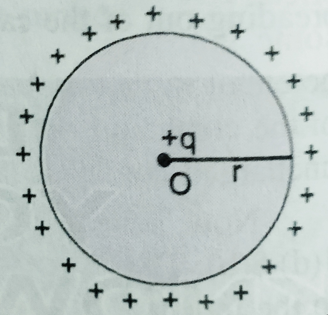
    Suppose a conductor of radius ‘r’ with centre ‘O’ has given charge ‘Q’  then its potential increases by ‘V’ . here potential V= q/4∏ϵ0r

    As we know capacity C = Q/V = Q/( q/4∏ϵ0r) Or. C = 4∏ϵ0r  ; Here r is in meter and  C is in farad .

    As we can see C α r i.e larger the radius of the sphere and larger will be capacity of the conducting sphere .

    Using this formula we can find the capacity of the earth which is given as

    C= 4×3.14 x(1/9×109) x 6.4x 106 = 711 x 10-6F  or 711μF .

    For next topic of electrostatics  which is parallel plate capacitor -click here –

  • Gauss’s law and proof of Gauss’s law.

    Gauss’s law and proof of Gauss’s law.

    Gauss’s law and proof of Gauss’s law .

    In this topic we will learn Gauss’s law , derivation of gauss’s law , derivation of coulomb’s law using gauss’s law .

    Before to know about Gauss’s law and proof of Gauss’s law student must know electrostatic flux , to read the notes on electrostatic flux click here-

    Question in the examinations may be asked as –

    state and prove Gauss’s law , using gauss’s law derive Coulomb’s law.

    Gauss’s law in electrostatics –

    According to Gauss for a closed surface total flux  in the free surface is 1/ϵ0 times the total charge inside the closed surface.

    To download the pdf of Gauss’s law and proof of Gauss’s law click here-

  • Electric flux and area vector

    Electric flux and area vector

    Electric flux and area vector

    In this topic we will discuss about Electric flux and area vector .

    question may be asked as what is electric flux ? write its unit and dimension.

    Area vector and electric flux –

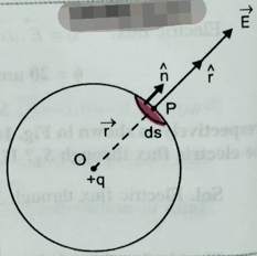
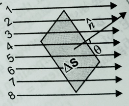
    As we know area is a scaler quantity , but in some cases or in case of some problems area is taken as vector quantity . the direction of area is taken as the normal of the surface at a given point . The vector associated with every area element of a closed surface is taken to be in the direction of the outward drawn normal .


    Electric flux – Electric flux over an area in an electric field is the total number of field line passes through that area normally .  It is denoted by ɸ its unit is Nm2C-1 . And its dimension is  [M1L3T-3A-1]. Electric flux is a scaler quantity.

    The  number of electric field lines crossing this area is  proportional to field intensity E . Let electric field lines makes an angle ϴ with the area vector dS , and E is the electric field intensity , then we can write  dɸ =  E. (dS cosϴ ) [ since dScosϴ is the component of area vector normal to the surface ].

    So ,  dɸ = E dS (With vector sign).

    Or,  ɸE = ∫E dS cosϴ

    To download the pdf of complete assignment related to Electric flux and area vector ( This pdf includes Gauss’s law and its applications). click here-

  • Equipotential surface

    Equipotential surface

    Equipotential surface and Relation between electrostatic field and potential

    In this topic we will discuss about  Equipotential surface and relation between electrostatic field and potential also,  we will know about equipotential surface for different-different conditions  .

     Equipotential surface- It is the surface inside the electrostatic field, the electric potential at every point on that surface are same. For any charge configuration, equipotential surface through a point is normal to the electric field at that point.

    Equipotential surfaces of a single point charge are concentric spherical surfaces centred at the charge .

    To download the complete notes on the topic, Relation between electrostatic field and potential click here-Equi-potential surface and Relation between electric field and electric potential

    Properties of equi-potential surfaces –

    (i) No work is done in moving a test charge from one point to another point on the equi-potential surface .

    (ii) Electric field is always normal to the equi-potential surface .

    (iii) No two equi-potential surface can intersect each other .

    (iv) Equi-potential surfaces is closer in the region of strong electric field and they are farther apart in the region of weak electric field .

    To view the related video click on the link given below –

     To download the notes on Equipotential surfaces and relation between electric field and electric potential click here-


  • Electrostatic potential energy and electrostatic potential

    Electrostatic potential energy and electrostatic potential

    Electrostatic potential energy and electrostatic potential

    In this topic we will discuss about Electrostatic potential energy and electrostatic potential also with potential difference , potential due to multiple charges and potential at a point due to electric dipole .

    To download  pdf of complete topic click here-

    Electrostatic potential energy –  Electrostatic potential energy of a charge in an electrostatic field is the amount of work done required to bring that charged body from infinity to that point .  Its unit is joule

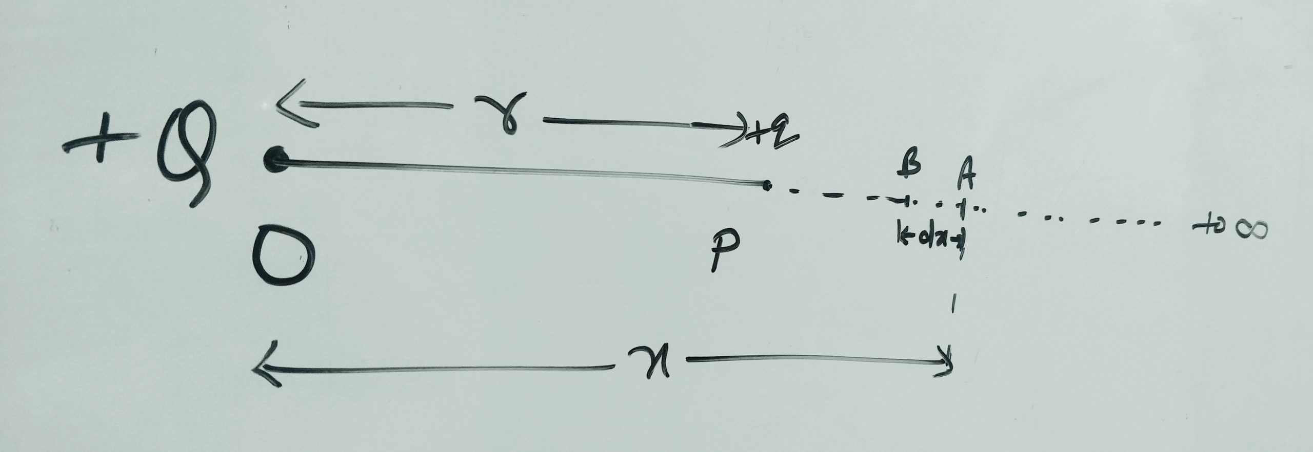
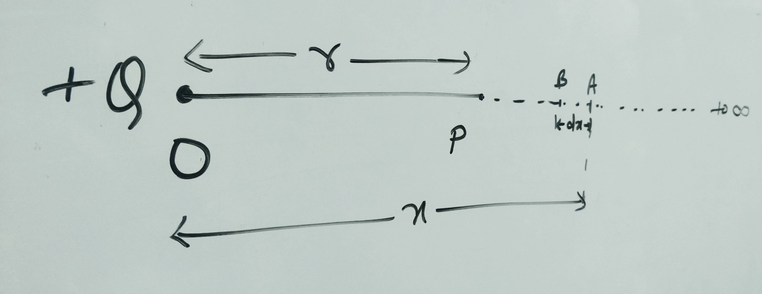
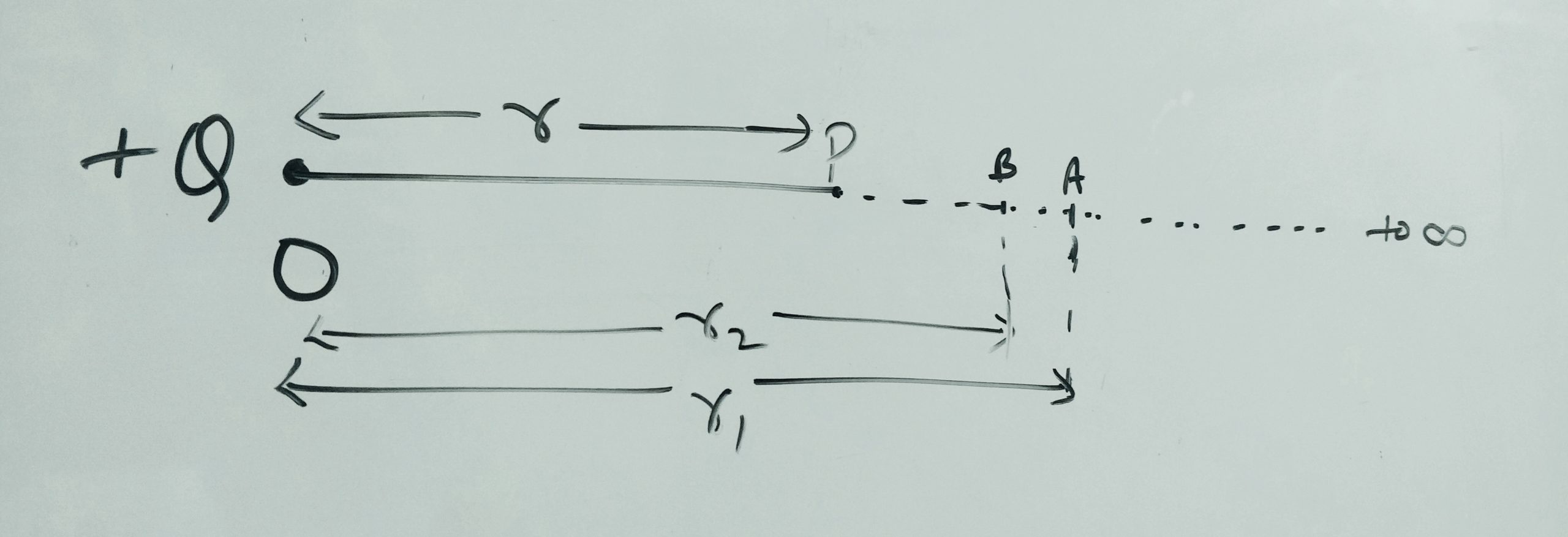
    Let a charge Q is placed at point O as shown in figure , we have to find the potential energy at point ‘p’ which is ‘r’ distance away from the point ‘O’  . ( derivation of this topic , link is given below)


    To see the video for electrostatic potential energy and electrostatic potential click on the link given below-

    Electrostatic potential – electrostatic potential at any point in a region of electrostatic field is the minimum work done required to carry a unit positive charge from infinity to that point .

    We can write  electrostatic potential  V = U/q   i.e.  electrostatic potential is equal to potential energy per unit charge .  Its unit is J/C .   or JC-1  or NmC-1 and its dimension is [M1L2T-3A-1]

    ( derivation of this topic , link is given  Above/below)


    Electrostatic potential difference –  Electrostatic  potential  difference between two points is the amount of work done required to bring the unit positive charge from one point to another point .

    ( derivation of this topic , link is given  Above/below)

    To view the video related to the topic potential difference and potential at a point due to multiple charges visit on the link given below-

    Electrostatic potential  at a point due to dipole- ( derivation of this topic , link is given below) . Before to know about this topic students must have to know about electric dipole , to read about electric dipole click here- 

    To view the video related to the topic electrostatic potential at a point due to a dipole visit to the link given below-


    Electrostatic forces are conservative  are  conservative in nature i.e. electrostatic force is independent of path followed , it only depends on initial and final position of the charge particle in an electric field .

     TO download complete notes of Electrostatic potential energy click here-