Author: Nayan Jha

  • current objective assignment -1

                                             Current objective assignment – (1)

                                       Electric conduction ohm’s law and resistance.

    Answers of all the questions are given at the end of all questions of the assignment.

    1. for which if the following depends of drift velocity v on electric field E is Ohm’s law obeyed ?          (a) v α E    (b) v= constant    (c) v α E ­½      (d)  v α  E 2   .

    2. A potential difference is applied across the end of the metallic wire . If the potential difference is doubled , the drift velocity ;     (a) will be doubled,  (b) will be halved,   (c) will be quadrupled,   (d) no change .

    3. The maximum current that flows in the fuse wire , before it blows out , varies with the radius r as :(a) r3/2    (b)  r     (c) r2/3   (d) r ½

    4. The mass of three wires of copper are in the ratio of 1:3:5 and their length are in the ratio 5:3:1 . T he ratio of their electric resistance is ;   (a) 1:3:5  (b) 5:3:1 (c) 1:15:125 (d) 125:15:1

    5. The temperature (T) dependence of resistivity  of a semiconductor represented by :

    6. A wire of resistance R b= is stretched till its radius is half of its original value . Then the radius of the stretched wire is ; (a) 2R   (b) 4R   (c) 8R    (d) 16R   :

    7. A wire till its length is doubled of its original length , then the resistance of the stretched wire is; (a) 2R   (b) 4R   (c) 8R    (d) 16R   :

    8. If a copper wire is stretched to make it 0.1% longer, then the percentage change in its resistance is approximately (a) 0.1% (b) 0.2 %  (c) 0.4% (d) 0.8% .

    9. If a copper wire is stretched to make its radius decrease by 0.1% , then the % change in its resistance is approximately ; (a) 0.1% (b) 0.2 %  (c) 0.4% (d) 0.8% .

    10. A current of 5 amp exist in the 10 ohm resistance, for 4 minutes . How many coulombs pass through any cross-section of the resistor in this time ? (a) 12 (b) 120 (c) 1200 (d) 12000.

    11. The temperature coefficient of resistance of a wire is 0.00125/0C at 300K is one Ohm. The resistance of the wire will be 2 ohm at (a)1154K (b) 1100k (c) 1400k (d) 1127k .

    12. Drift speed of electrons is of the order of ; (a) zero (b) 10-2 (c) 105 (d) 100m/s ;

    13. Which represents the negative dynamic resistance?  

     (a) AB   (b) BC  (c)CD  (d) DA

    14. When a current flows in a wire , there exist in electric field in the direction of ;                               (a) flow of current, (b) opposite to the flow of current (c) perpendicular to the flow of current (d)at the angle of 450 to the flow of current.

    15. The drift velocity of free electron in a conductor is v when a current I is flow in it . If both the radius and current are doubled , then drift velocity will be;   (a) v (b) v/2 (c) v/4 (d) v/8 .

    16. The sides of rectangular block are 2,3 and 4cm . the ratio of maximum to minimum resistance between its parallel face is;    (a) 4    (b)3   (c) 2   (d) 1 ;

    17. The electric resistance of certain wire is R, if its length and radius both are doubled , then  ;        (a) resistance will be doubled and the specific resistance will be halved  (b) resistance will be halved and the specific resistance will be remain same  (c) resistance will be halved and the specific resistance will be doubled  (d) resistance will be unchanged and  also the specific resistance will be unchanged.

    18. Total no. of electrons present in 4 amp current flowing for 1 sec is ;  (a) 2.5 x 10⁹ (b)2.5x 10²⁰ (c) 1.25×10¹³ (d) 6x 10⁸ .

    19. If the electric current through a bulb is 3.2 A, the no of electrons flowing through it in 1 sec is;    (a) 2 x 10⁹  (b) 2 x 10¹⁹ (c) 3.2 x 10⁹ (d) 1.6 x 10¹⁸ .

    20. The resistance of a wire is 5 ohm at 500c and 6 ohm at 1000c , the resistance of the wire at 00c will be;    (a) 3 ohm (b) 2 ohm (c) 1 ohm (d) 4 ohm .

    21. Two wires have length ,diameter and resistivity  all are in the ratio 1:2 the resistance of the first wire is 10 ohm, the resistance of the second wire is     ; (a) 5 (b) 10 (c) 20 (d) infinity.

    22. Two copper wire have their masses in the ratio 2:3 and the length in the ratio 3:4 , the ratio of their  resistance is  ;     (a) 4:9 (b) 27:32 (c) 16:9 (d) 27:128 (e) 1:2 ,

    23.On increasing the temperature of the conductor  its resistance increases because the  ;                 (a) relaxation time increases (b) mass of electron increases (c) electron density decreases (d) relaxation time decreases .

    24 .The resistance of a wire is R ohm . It is melted and stretched to n times its original length , the new resistance will be ; (a) R/n (b) n2R (c)R/ n2 (d) nR .

    25. The current flowing through a wire depends on time as I = 3t2 +2t +5 . The charge flowing through the cross-section of the wire in time from t=0 to t=2 sec is; (a) 22c (b) 20c (c) 18c (d) 5c.

    ans- Ans- 1-a   ;2- a   ; 3-a  ;4- d  ;5-b  ;6-d  ; 7-b ; 8-b ; 9-c  ;10-c ;  11-d; 12- b ; 13 -c;  14-a  ;15-b  ;16- a;  17-b ; 18-a ; 19-b  ; 20-d ; 21-b ; 22-b  ; 23-d   ;24-b  ;25-a
  • Very important questions of ray optics

    Very important questions of ray optics

    Very important questions of ray optics-

    In this topic we will get some, Very important questions of ray optics. Students preparing for board examination must solve all the questions given below.

    Very important questions of ray optics

    1. Derive the mathematical relation between refractive indices μ1 and μ2 of two radii and radius of curvature R for refraction at a convex spherical surfaces. Consider the object to be a point source on the principle axis in rarer medium of refractive index  μ1 and a real image formed in the denser medium .

    Light from a point source in air falls on a convex spherical glass surface of refractive index 1.5 and radius of curvature 20 cm . The distance of light source from the glass surface is 100cm . At what position the image will be formed?

    2. A point object is placed in front of a double convex lens with its spherical faces of radii of curvature R1 and R2 . Show the path of rays due to refraction at first and subsequently at the second surface to obtain the formation of the real image of the object. Hence obtain the lens maker’s formula for a thin lens.

    (i)   A double convex lens having both faces of the same radius of curvature has refractive index 1.5. Find out the radius of curvature of the lens required to get the focal length of 20 cm . (ii) How the focal length of the above lens changes when it is placed in liquid of refractive index (a) 1.3 (b) 1.5 and (c)2.5 .

    To solve this questions students must watch this video

    3. Draw the ray diagram to show the refraction of a ray of monochromatic light passing through a glass prism. Deduce the expression for the refractive index of glass in terms of angle of prism and angle of minimum deviation.

    A ray of light incident on face AB of an equilateral glass prism ABC , shows minimum deviation of 300 calculate the speed of light through the prism. Also find the angle of incidence at face AB so that the emergent ray along the face AC .

    4.What do you mean by the term total internal reflection also write the conditions to get the total internal reflection, define the term critical angle for a pair of media , how the critical angle is related to the refractive index of the medium. A point source is kept at the bottom of the pond 2m deep ( μ= 4/3 )draw the ray diagram and calculate the area of water surface through which light emerges out of the pond.

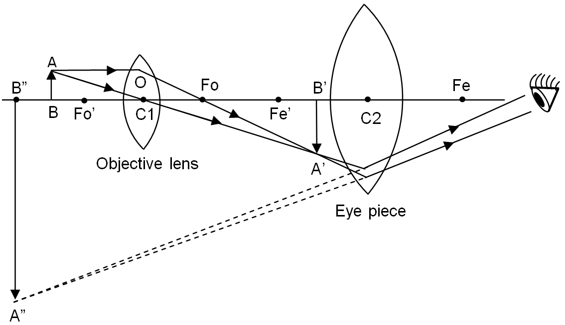
    5. Draw a ray diagram showing the image formation of compound microscope, hence obtain the expression for magnifying power when (I) image is formed at infinity (II) image is formed at least distance of distinct vision. (a)Why must both the objective and eyepiece of a compound microscope have short wavelength? (b) while viewing through a compound microscope, why should our eyes be placed not on the eye piece but at short distance away from it for best viewing?

    TO WATCH THE COMPLETE VIDEO OF THIS TOPIC CLICK ON THE VIDEO GIVEN BELOW-

    6. Draw a labelled ray diagram of astronomical telescope, for(I) normal adjustment, (II) at least distance of distinct of vision. Also derive the expression for magnifying power .You are given the three lance L1 , L2 , L3 having power 3D , 6D and 10D respectively with aperture 8cm,1cm and 1cm respectively, which two lances will you use as an eyepiece and objective to construct (a) compound microscope and (b) Astronomical telescope. Give reasons.

    7.Explain reflecting type telescope draw the ray diagram for (I) Newtonian and (II)Cassegrainian type telescope. Write advantages of reflecting type telescope over refracting type telescope.

    8.Derive lens formula in a convex lens using suitable ray diagram 1/v -1/u = 1/f . (a) A convex les is used to obtain the image of an object on the screen 10 cm from the lens . if the magnification is 19, find the focal length of the lens. (b) An illuminated object and a screen are placed 90 cm apart. Determine the focal length and nature of the lens required to produce a clear image on the screen , twice the size of the object.

    TO WATCH THE COMPLETE VIDEO OF THIS TOPIC CLICK ON THE VIDEO GIVEN BELOW-


  • Magnetic elements of earth

    Magnetic elements of earth

    In this topic we will discuss about the magnetic elements of earth. All three kinds of magnetic elements of earth , angle of dip,angle of declination and horizontal components of earth magnetic field.

    Before to know about this topic students must know the magnetic field of earth. To get the note on this topic Magnetic fields of earth click here-

    Magnetic elements of earth –

    Magnetic elements of earth at a place are the quantities which describe completely the magnitude and direction of magnetic field at that place.

    There are three magnetic elements of earth-

    (i) Magnetic declination (ϴ);

    (ii) Magnetic inclination or angle of dip (ẟ);

    (iii) Horizontal components of earth’s magnetic field(H).

    (i) Magnetic declination (ϴ);-

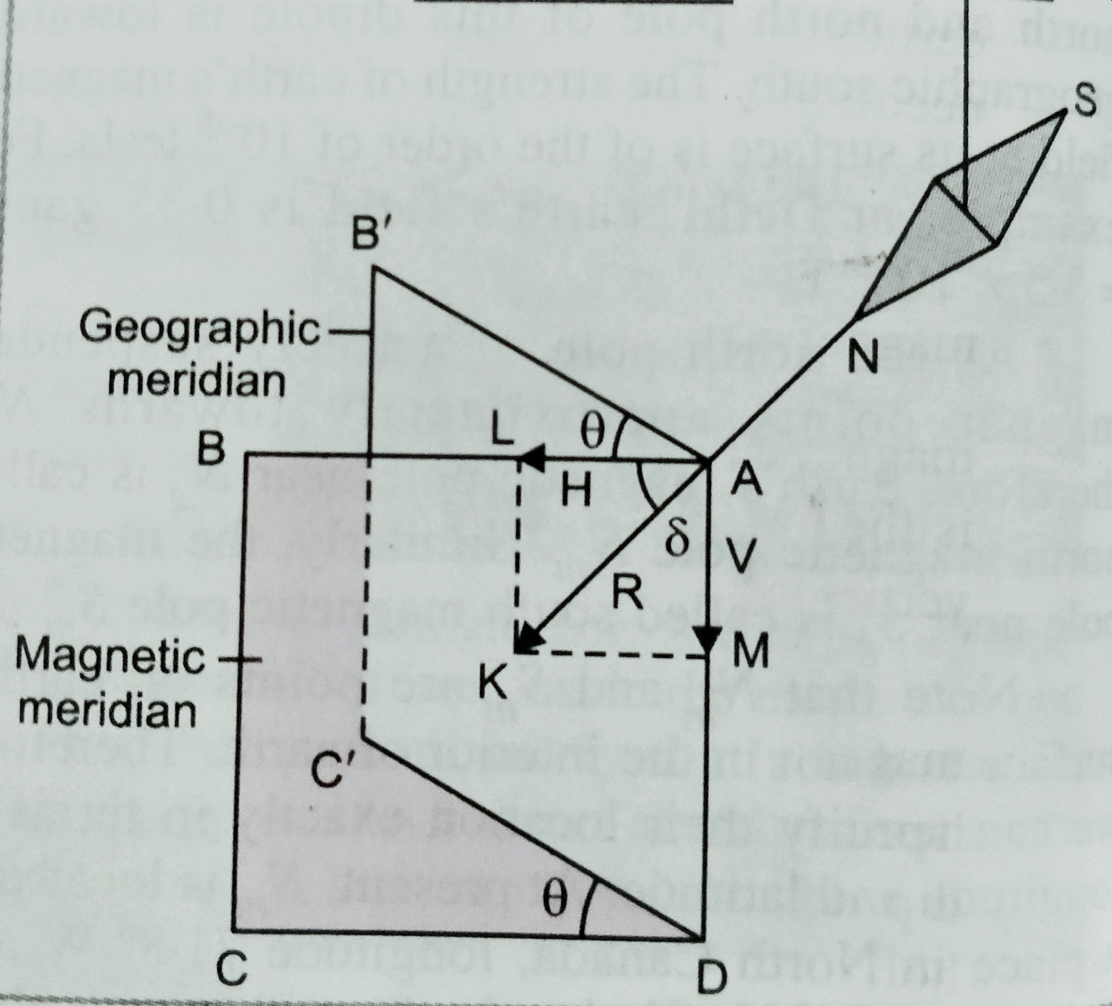
    The small angle between magnetic and geographic axis at a place is known as magnetic declination at that place .

    Or, In other words we can define , angle between geographic and magnetic meridian at a place on earth is known as the magnetic declination at that place.

    (ii) Magnetic inclination or angle of dip –

    Magnetic inclination at a place on the earth is the angle between total strength of magnetic field and horizontal lines in magnetic meridian.

    The value of angle of dip at a place on the earth is measured using an instrument called ‘ Dip circle’.

    (iii) Horizontal component-

    It is the components of total field strength of earth’s magnetic field in the horizontal direction in magnetic meridian.

    As shown in figure.  , total field strength is represented by AK and angle <BAK = ẟ

    Then the magnetic field along AB ( horizontal) is given as

    H = R cos ẟ………..(i)

    And magnetic field along AD is given as V= R sin ẟ  ………….(ii)

    Squiring and adding equation (i) and (ii) is given as

    H2 + V2 = R2 ( Cos2ẟ+ Sin2ẟ) ;

    So , R = √( H2 + V2)  …………(III)

    Again if we divide  (ii) by (i) we get

    R sinẟ/Rcosẟ = V/H

    Or,  Tan ẟ = V/H …………………(iv)

    [**** important information about angle of dip –

    (1). At a place on the magnetic poles , total earth’s magnetic field is perpendicular to the surface of earth .( ẟ=900 )

    So, H = R cos 900 = 0

    It means R = V  ( total magnetic field is only in vertical direction)

    (2) At a place on equator , total magnetic field is parallel to the earth ( ẟ=00)

    So , V= Rsin00 = 0

    It means R = H ( total magnetic field is in horizontal direction).

    (3) In a vertical plane at an angle ϴ with the magnetic meridian.

    Then apparent H’ = H cos ϴ

    Again, apparent V’ = V,

    Therefore tanẟ’ = V’/H’ = V/Hcosϴ = tanẟ/cosϴ   ;   (ẟ’ is the apparent value of angle of dip).

    (4) If ẟ1 and ẟ2 are observed angle of dip in two arbitrary vertical planes which are perpendicular to each other then the true angle of dip ẟ is given as –

    Cot2ẟ=cot2ẟ1 + cot2ẟ2.

    (5) If λ is the magnetic latitude at a place, then it can be shown that the angle of dip at that place is given as ,   tanẟ = 2 tan λ …]


  • Magnetic field of earth

    Magnetic field of earth

    In this topic we will discuss about Magnetic field of earth. And also cause of earth’s magnetism, and magnetic and geographic axis and meridian.

    Magnetic field of earth –

    In 1600 Sir William Gilbert first suggested that earth behaves like a magnet , it is huge magnet itself. The following evidence explain it-

    1. When a magnet suspended freely then it always comes in rest along the north south direction.

    2.When  we put a soft iron piece under the surface of earth in the north south direction, then it acquire the properties of magnet after some time .

    1. When we draw the field lines of a magnet, we come across neutral points . At these points  magnetic field of the earth  neutralize magnetic field due to the magnet .

    Cause of earth magnetism –

    Some important postulates are given below , but exact cause is still unknown-

    1. In 1600 William Gilbert suggested that the earth itself is a huge magnet.

    2. According to Prof. Brackett , due to the rotation of earth , about its axis earth gets magnetic property , and starts behaving like a magnet. Every substance on the earth behave as a charge particle due to rotation of earth. It is a circulating currents develops due to charge particle , which are responsible for the magnetization .

    1.  As earth rotates , strong electric currents are setup due to movement of charged ions these current might be the cause of magnetization of earth.

    4.Since earth core is very hot and molten which circulates the ions of Iron, Nickel in the highly conducting liquid region of the earth’s core might be forming current loops and producing earth’s magnetic field.

    Important topic with Magnetic field of earth, is given below-

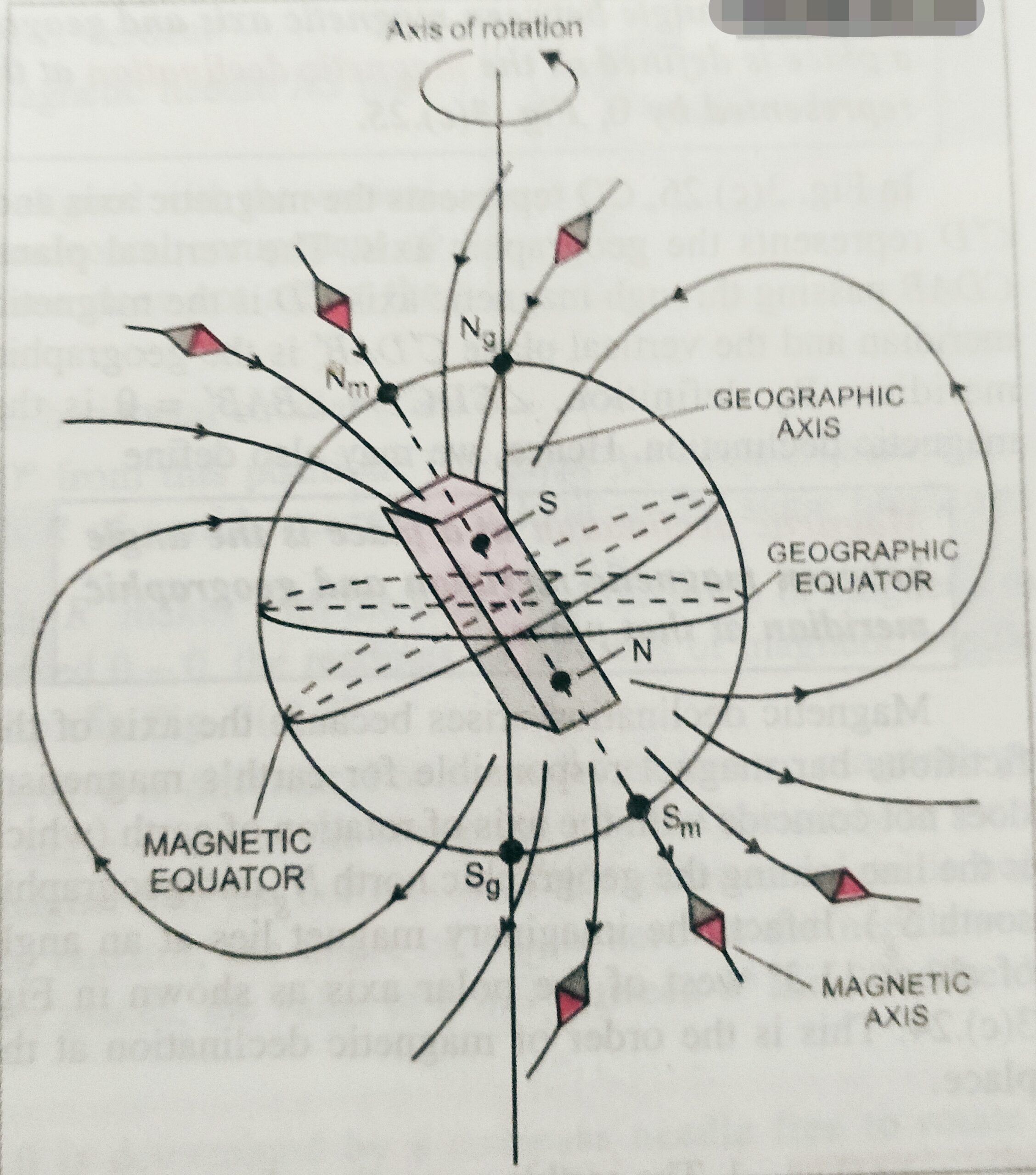
    Straight line passes through the geographic north and south pole is called  geographic axis.  and the straight line passes through the magnetic north and south pole is called magnetic axis.

    The very large circle on the earth perpendicular to the magnetic axis is called magnetic equator.

    The vertical plane passing through the geographic north and south pole is called geographic meridian, and the vertical plane passing through the magnetic north and south pole is called magnetic meridian.

    Next topic magnetic elements of earth-

    To get the notes on magnetic elements of earth click here-


  • Conversion of galvanometer into voltmeter

    Conversion of galvanometer into voltmeter

    Conversion of galvanometer into voltmeter

    In this topic we will discuss about the ‘ Conversion of galvanometer into voltmeter ‘ . What is ammeter? and how can we convert a Galvanometer into voltmeter?

    Before to read this topic ‘ Conversion of galvanometer into voltmeter ‘  students must know about the galvanometer and shunt .

    To get the notes on galvanometer click here-

    To get the notes on shunt click here-


    This topic is very important topic  for class 12th board examination and for other competitive examination ( for medical and engineering entrance examinations )

    Voltmeter-

    It is high resistance galvanometer used to measure potential difference between two points of a conductor or circuit.

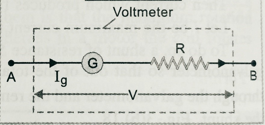
    A galvanometer can be converted into voltmeter by connecting high value resistance in series with the galvanometer( as shown in figure).

                    To get the syllabus of class 12th physics click here-

    Let, G is the resistance of the galvanometer,

    IG  is the current passes through the galvanometer,

    R is the high value resistance  in series with the galvanometer.

    Let,

    V is the potential difference of the galvanometer.

    So we can write V = IG ( R + G)

    Hence  R =( V/IG)- G ;

    Resistance of the voltmeter Rs = R + G ;

    So we can say ,for ideal voltmeter the resistance of the voltmeter should be infinity.

    This topic is very important for all state  class 12th board examination and for other entrance examination , therefore it is important to solve the assignment of this topic .

    In the assignment , we provide all kind of questions like , objective , short answer type, long answer type , numericals and hots . After solving the assignment of this chapter students will be able to improve there knowledge on this chapter.

    To get the complete assignment of magnetic effect of current click here-

    But students must solve the questions base on its previous topic.

    We are providing the link , so that students should clear all topic of this chapter- click here for ammeter

  • Conversion of galvanometer into ammeter

    Conversion of galvanometer into ammeter

    Conversion of galvanometer into ammeter

    In this topic we will discuss about the ‘ Conversion of galvanometer into ammeter ‘ . What is ammeter? and how can we convert a voltmeter into ammeter?

    Before to read this topic ‘ Conversion of galvanometer into ammeter ‘  students must know about the galvanometer and shunt .

    To get the notes on galvanometer click here-

    To get the notes on shunt click here-

    This topic is very important topic  for class 12th board examination and for other competitive examination ( for medical and engineering entrance examinations )

     Ammeter –

    It is a low resistance galvanometer used to measure the electric current in a circuit.

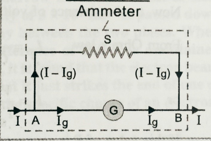
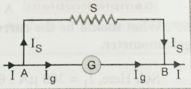
    Let, I and IG are the total current passes through the circuit and the galvanometer respectively. G , and S are the resistances of the galvanometer and shunt respectively.

       To know the syllabus of class 12th board  examinations ( CBSE ) click here-

    As shown in figure,  potential across S is VS = (I- IG ) S

    Potential across  G is  VG = IG G

    Since both are in parallel combination , hence  is  VS = VG

    So, ( I-IG) S =  IG G

    S=  IG G/( I-IG) ……………………….( i)

    Using this  equation we can find the value of shunt to get the ammeter of our desired value.

    Resistance of the Ammeter ;  Let R is the resistance of the ammeter.

    Then we can write ;  1/g  + 1/s = 1/ R

    R = S+G/SG ;

    For ideal ammeter value of R should be  zero.

    After studding this topic students can visit the next topic which is conversion of galvanometer into voltmeter. To get the next topic click on the link given below.

    NEXT TOPIC -CONVERSION OF GALVANOMETER INTO VOLTMETER. CLICK HERE-

    To get the notes on the complete assignment of moving coil galvanometer click here-

    To get the notes on objective questions of moving coil galvanometer click here-

  • Shunt

    Shunt

    Shunt

    In this topic we will discuss about, what is shunt? what are the uses of shunt? and how can we convert a galvanometer into ammeter?

    Before to go with this topic students must know about the moving coil galvanometer, to get the notes of moving coil galvanometer click here-

    Shunt-

    Shunt is a low resistance connected in parallel with the galvanometer or ammeter to protect it from high current. It is used to convert the galvanometer into an ammeter, by connecting it in parallel.

    When high value current passes through the galvanometer or a low range ammeter then it can damage the instrument . To overcome this difficulties a low value resistance(shunt) is connected in parallel , so that maximum current can pass through the shunt ,and instrument will remain  safe.

    Let, I ,IS and IG are the total current passes through the circuit , galvanometer and circuit respectively. G , and S are the resistances of the galvanometer and shunt respectively.

    As shown in figure,  potential across S is VS = IS S

    Potential across  G is  VG = IG G

    Since both are in parallel combination , hence  is  VS = VG

    So,  IS S =  IG G

    But Is = I – IG

    So we can write , ( I-IG ) S =  IG G ;and hence  IG = I (S /S+G)

    Similarly , IS = I (G /S+G) ;

    This result shows that shunt can be used as the (i) convert the galvanometer into ammeter and (ii) To increase the range of galvanometer.

    NEXT TOPIC CONVERSION OF GALVANOMETER INTO AMMETER. CLICK HERE-

  • Torque on a current carrying coil placed in magnetic field

    Torque on a current carrying coil placed in magnetic field

    Torque on a current carrying coil placed in magnetic field .

    In this topic we will find the expression for the torque on a current carrying coil placed in magnetic field. But before to derive the expression for ‘Torque on a current carrying coil placed in magnetic field’ , students must know the expression for the force experienced on the current carrying coil placed in uniform magnetic field. To get the notes on this topic click here-

    To get the syllabus of physics class 12th, click here-

    Torque on a current carrying coil placed in a magnetic field-

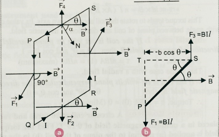
    Suppose a rectangular coil PQRS carrying current I is placed in a uniform magnetic field B as shown in figure ( a) .

    Let,  PQ = RS = l and QP=SP=b , suppose I is the current flowing through the coil.

    Let, ϴ is the angle between the plane of the coil with the magnetic field.

    As we know force on a current carrying coil is given as F = BIL sinϴ ,

    Then we can find force on PQ is given as , F1 = BIl sinϴ [ but ϴ=900]

    Therefore,  F1 = BIl sin900  out side the plane ( using Fleming’s left hand rule)

    Similarly, we can find force on SR is given as , F3 = BIl sinϴ [ but ϴ=900]

    Therefore,  F3 = BIl sin900   Inside the plane ( using Fleming’s left hand rule).

    Again,  Force on QR is given as , F2 = BIb sinϴ

    Therefore,  F2 = BIb sinϴ  directed downward ( using Fleming’s left hand rule),

    And again, Then we can find force on SP is given as , F4 = BIb sinϴ

    Therefore,  F4 = BIb sinϴ  directed upward ( using Fleming’s left hand rule)

    It is clear that F2 and F4 will cancel out each other,

    But due to pair of force F1 and F3 these force form a couple , and cause of turning effect,

    So, torque Ʈ = either force x perpendicular distance

    = F1 bcosϴ = BIlb cos(90-α)=BIl sinα ;

    But here lx b = area ‘A’, ; So we can write , Ʈ= BIA sinϴ,

    If there are N number of turns in the coil then we can write net torque , Ʈ= BI NA sinϴ.


    Next topic – Moving coil Galvenometer click here.

  • Force between two parallel current carrying linear conductors

    Force between two parallel current carrying linear conductors

    Force between two parallel current carrying linear conductors

    In this topic we will find the expression for Force between two parallel current carrying linear conductors when they are separated by some distance , and current flowing through them is in same direction ( also when current flowing through them is in different directions).

    Before to know about In this topic  expression for Force between two parallel current carrying linear conductors when they are separated by some distance, students must know the expression for current carrying conductors placed in uniform magnetic field. To know about this topic click here

    Force between two parallel current carrying linear conductors –

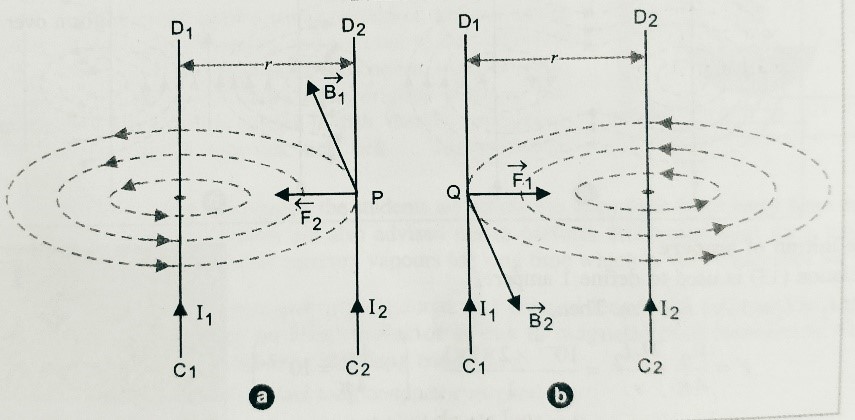
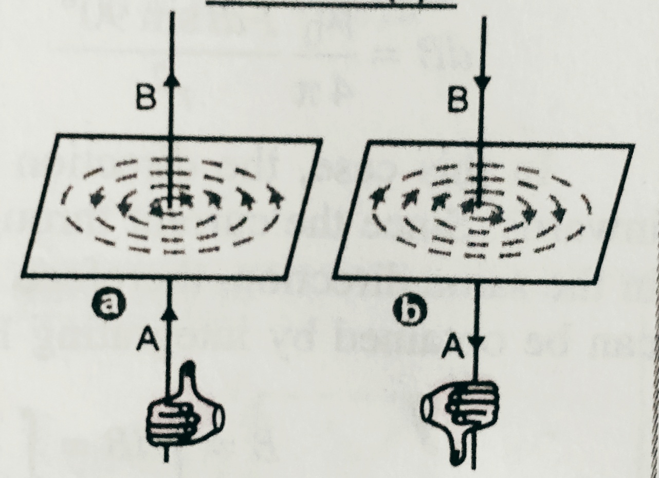
    Two long straight conductors are placed parallel two each other at distance ‘r’  and current flowing through them are I1 and I2 . Since each conductors are carrying current produces magnetic field and hence each conductor experience force on each other.

    As shown in figure (a) due to current I1 through C1D1­ magnetic field at a point P on the wire C2D2 is B1 , then   B1 =  μ0I1 /2∏r ,

    Since current flowing through the wire C2D2 is I2,

    Then force experienced on the wire C2D2 is given as ,

    F2 = B1 I2 l

    Then  , Force per unit length F2/l = B1 I2 = μ0I1I2 /2∏r (Towards left i.e. towards C1 D1) .

    Similarly , As shown in figure (b) due to current I2 through C2D2­ magnetic field at a point Q on the wire C1D1 is B2 , then   B2 =  μ0I2 /2∏r ,

    Since current flowing through the wire C1D1 is I1,

    Then force experienced on the wire C1D1 is given as ,

    F1 = B2 I1 l

    Then  , Force per unit length F1/l = B2 I1 = μ0I1I2 /2∏r (Towards right i.e. towards C2 D2) .

    So we can say if the current through each wire are in same direction then there will be force of attraction between them .

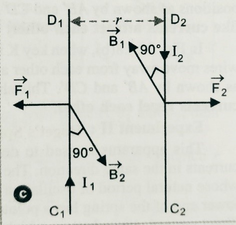
    If the direction of current in the both the wires are opposite then there will be force of repulsion between them, as shown in figure ( c )below, with the same force  μ0I1I2 /2∏r .

  • Complete assignment of magnetic effect of current

    Complete assignment of magnetic effect of current

    Complete assignment of magnetic effect of current

    In this assignment Complete assignment of magnetic effect of current all kind of questions , objective , short answer type questions, long answer type questions and all kind of numericals with hots questions.

    Before to solve this assignment students must know the syllabus  and notes related to this chapter magnetic effect of current.

    After solving these questions students will be able to solve the all kind of questions related to this chapter. Specially objective type question will help the students to solve the questions for all competitive examinations like JEE and NEET along with board examinations.

    TO download complete assignment of magnetic effect of current click here-

    Some of the examples of Multiple choice – ( Answers of all the multiple type questions given below ; after the multiple type questions)

    1. Magnetic induction is measured in:
    • (a)weber (b) weber/m
    • (c) weber/m2    (d) weber/m3
    1. The force acting on a charge q moving with a velocity ʋ in a magnetic field of induction B is given by:
    • (a)q/(ʋ ₓ B)   (b) (ʋ ₓ B)/q
    • (c) q/(ʋ ₓ B)  (d) (ʋ . B)q
    1. Two free parallel wire carrying currents in the opposite directions:
    • (a) attract each other
    • (b) repel each other
    • (c) do not affect each other
    • (d) get rotated to be perpendicular to each other
    1. Two parallel wires carrying currents in the same direction attract each other because of:
    • (a) potential difference between them
    • (b) mutual inductance between them
    • (c) electric forces between them
    • (d) magnetic force between them
    1. A free charged particle moves through a magnetic field. The particle may undergo a change in:
    • (a)speed         (c) direction of motion
    • (b)energy       (d) none these

    To download complete assignment of Complete assignment click on the link given below-

    complete assignment of magnetic effect of current