Category: 12th Notes

  • Combination of resistances

    Combination of resistances

    Combination of resistances

    In this topic we will discuss about combination of resistances , i.e series and parallel combination of resistances .

    Combination of resistances –

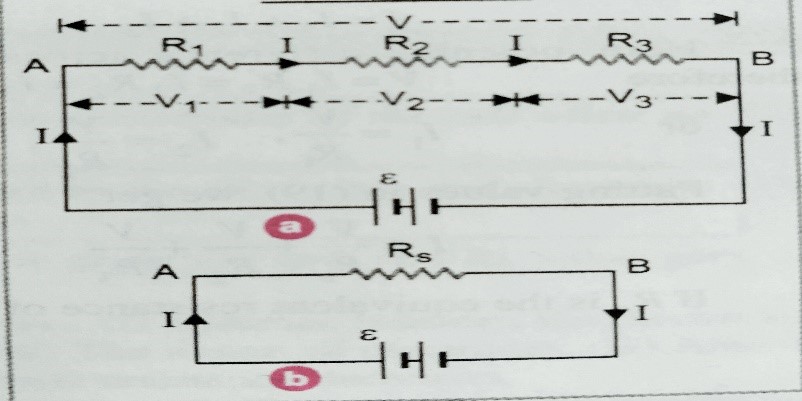
    Series combination –  In series combination resistors are connected end to end with one another . resistors are said to be connected in series , when same current passes through the resistors  when potential difference applied across the connected  resistors .

    Let , three resistors  of resistance R1, R2,and R3 are connected in series with external source E as shown in figure (a) . Let  I be the current flowing through the each resistors , their respective potential differences are V1, V2 and  V3 .

    According to Ohm’s law  here,  V1 = I R1  ,    V2 = I R2   ,  and   V3 = I R3

    Let, RS is the equivalent resistance of the combination as shown in figure (b) ,

    then , V = I RS

    But net potential V = V1+ V2 +V3

    Then  IRS  = I R1 + I R2 + I R3

    So ,  RS  =  R1 +  R2 +  R3  ……………………This the equation of equivalent resistance .

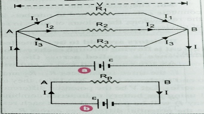
     Parallel combination –  Two or more resistors are said to be in parallel if potential difference across each resistors are same but currents are different . In parallel combination one end of each resistors are connected at one point and other ends at another point .

    Let three resistors of resistance R1 , R2 and R3 are connected in parallel as shown in figure (a) with external source . let V be the potential difference of the end A and B . I1, I2 and  I3 are the currents flowing through the resistors .


    According to Ohm’s law  I=V/R .

    SO, I1=V/R1 , I2=V/R2 and I3=V/R3

    Let, Rp is the equivalent resistance of the combination as shown in figure (b)

    Then I=V/Rp

    But I = I1+ I2 + I3

    V/Rp = V/R1 + V/R2 + V/R3

    SO, 1/Rp = 1/R1 + 1/R2 + 1/R3 …………………….. equation for equivalent resistance .


  • Current density , conductance and electrical conductivity

    Current density , conductance and electrical conductivity

    Current density , conductance and electrical conductivity  –

    In this topic we will discuss about what is Current density , conductance and electrical conductivity  ? and also the relation between them .

    Before to learn about this topic students must have to know about Drift velocity , Ohm’s law , resistance and resistivity ( without know about them students can’t understand this topic explained below )

    To  know about drift velocity click here-

    To know about Ohm’s law click here-

    To know about resistance and resistivity click here-

    Current density , conductance and electrical conductivity  –

    Current density –

    Current density of a conductor at a point is the amount of current flowing per unit area of the conductor .

    If ‘I’ is the current flowing through the conductor and A is the area of cross-section the conductor at a given point then current density  J = I/A . Its unit is ampere per meter square ( Am-2)

    Again as we know  I = neA Vd ;

    Then current density J = neA Vd /A =  ne Vd

    Conductance (G) of a resistor –

    Conductance of a conductor is the inverse of resistance (R) .

    G = 1/R   , Its unit is ohm-1 or mho or siemen (S) ;

    Electrical conductivity –

    Electrical conductivity is the inverse of resistivity . It is represented by (σ) .

    So, σ = 1/ƍ  its SI unit is ohm-1m-1  ,

    and its dimension is [ M-1 L-3 T3 A2]

    So we can write  electrical conductivity , σ = ne2Ʈ/m


    Relation between J , E and σ

    [ microscopic form of Ohm’s law ]-

    I =neAVd = neA (eEƮ/m) = nAe2EƮ/m

    Or   J=I/A   = (nAe2EƮ/m)/A = E/ƍ = E(1/ƍ)=Eσ

    J=Eσ

    Relation between electrical resistivity and electron mobility –

    As we know , I =neAVd ; Vd = μ(mobility)E

    And  J = I/A = E/ƍ = neVd =neEμ    or , ƍ=1/neμ . 


     Next topic colour code of  carbon resistors – click here-


  • Colour code for carbon resistor

    Colour code for carbon resistor

    Colour code for carbon resistor –

    In this topic we will discuss about Colour code for carbon resistor .In which we will know that how can we find the value of carbon resistor .

    Before to know about this topic  Colour code for carbon resistor students must have to learn about resistance and resistivity .

    To learn about resistance and resistivity- click here-

    Colour code of carbon resistor –

    A carbon resistor are made by modulating carbon into a cylinder with wire leads at the two ends . such carbon resistor is encased in plastic jackets .

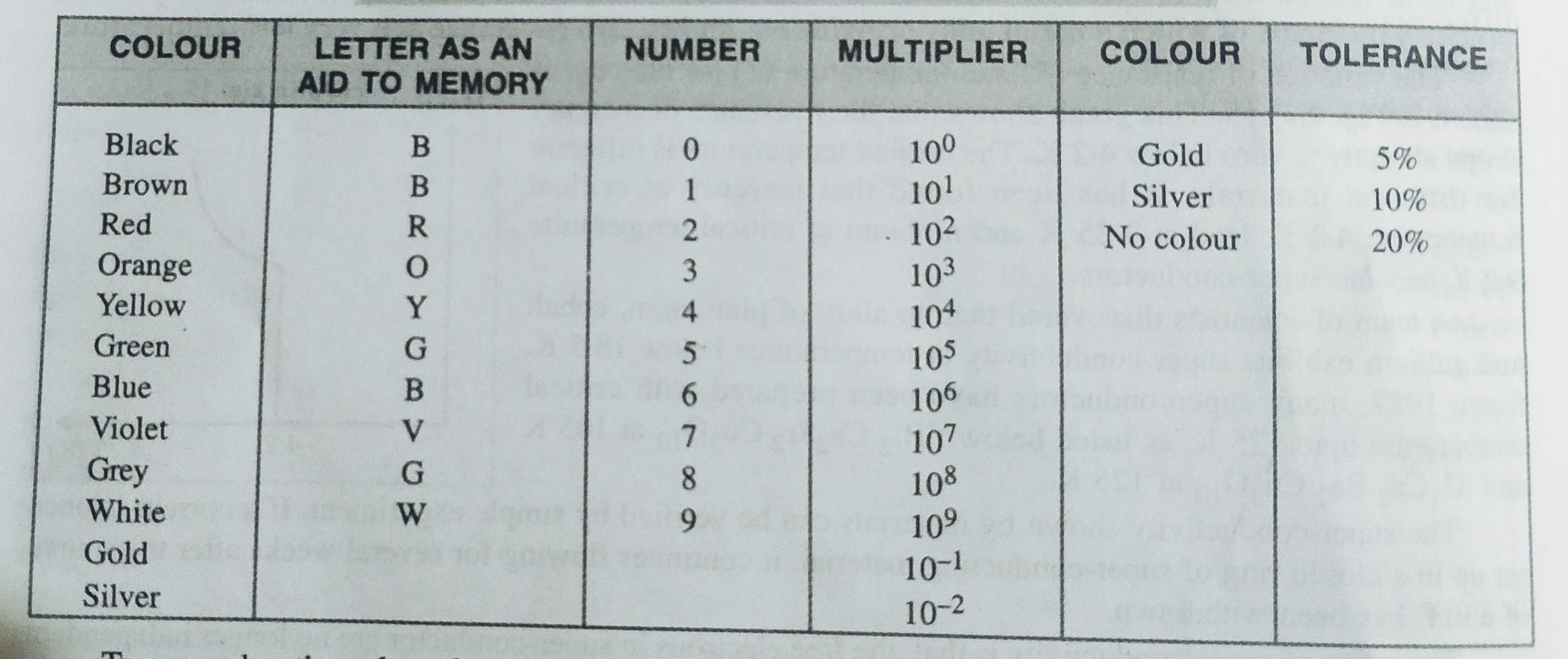
    The colour code for the carbon resistor is given in the table :-

    To remember the value of colour coding we must keep in my mind the following sentences :-

    B B ROY of Great Britain has Very Good Wife wearing Gold Silver Necklace

    [ here bold capital figure gives the first name of the colour shown in the table]


    Way to find the resistance of carbon resister –

    (i) Colour of the first strip A from the ends indicates the first significant figure,

    (ii) colours of the second strip B indicates the second significant figure of resistance,

    (iii) The colour of the third strip C indicates the multiplier,

    (iv) The colour of the fourth strip R indicates the tolerance limit of the resistance.

    [ note- if fourth strip is not given then tolerance will be 20%]


    Example- for the given carbon resistor, first strip be red, second strip be yellow, third be orange and fourth is gold. what is the resistance?

    Solution-    sequence of the colour band is – red, yellow, orange and gold

    Therefore, value of resistance of the given resistor =24 x 103 +- 5% Ohm;

  • Thermistors and superconductor

    Thermistors and superconductor

    Thermistors and superconductor –

    what do you mean by the term Thermistor and superconductor ? How a Thermistors is different from ordinary resistance and what are the applications of Thermistors and super-conductors?

    Before to learn about this topic Thermistors and superconductor , students must have to learn about resistance and resistivity;

    To learn about resistance and resistivity click here-

    Thermistors   –

    It is a heat sensitive device whose resistivity changes very rapidly with change of temperature . The temperature coefficient of resistivity of a thermistors is very high , which may positive or negative . a thermistors can have a resistance in the range of 0.1 ohm – 107 ohm .

    Uses of thermistors –

    Thermistors are used in industry as temperature control unit , remote sensing, picture tube and to measure very high temperature change .

    A thermistors differs from an ordinary resistance in the following ways –

    (i) The temperature coefficient of resistivity of a thermistors can be both positive and negative .

    (ii) The resistance of thermistors changes very rapidly with change in temperature

    (iii) temperature coefficient of resistivity of a thermistors is very high .


    Super-conductivity

    Super-conductivity is the property due to which a metal alloy or metal oxide shows zero resistance at a very low temperature . or in another words we can say that certain metals or alloys at very low temperature lose their resistance and becomes zero .

    Application of super-conductors –

    (i) It is used to produce very high speed computers ,

    (ii) it is used to transmission of electric power ,

    (iii) It is used to make very strong electromagnet ,

    (iv) It is used in material science research and high energy particle .


    To learn about Ohm’s law and prove of Ohm’s law and limitations of Ohm’s law; click here-


  • Electrical resistance and resistivity

    Electrical resistance and resistivity

    Electrical resistance and resistivity

    In this topic we will discuss about what is Electrical resistance and resistivity (specific resistance). On what factors Electrical resistance and resistivity depends ? And some plot of resistivity with temperature.

    Electrical resistance – 

    It is the property of a conductor to resist the flow of current  through it  or electrical resistance is the obstruction posed by the conductor to the flow of electric current through it . Or Resistance of a conductor is the ratio of potential difference applied across the end of the conductor to the current flowing through it .  i.e R=V/I  ; 

    the ratio of potential V/s current gives resistance, which is shown in Ohm’s law . 

    Its unit is Ohm (Ὡ) or Volt /Ampere = V/A

    And its dimension is  [ML2T-3A-2]

    We can define one ohm as –   resistance of a conductor is said to be 1 Ohm when 1 volt potential difference setup across the end of the conductor and current flows through the conductor is 1 Ampere .

    ( ********   Cause of the resistance –    As we know even a small piece of the conductor contains millions of free electrons when potential difference setup across the end of the conductors the electric field setup in the conductor due to which electrons start flowing from low to high potential , and the wire arise on account of frequent collision which oppose the flow of charges from one end to other . )

    Effect of temperature on resistance –   As we know resistance  R = ml/n Ae2 Ʈ

    For a given conductor  R α  1/Ʈ  when the temperature of the conductor is increases then the density remain constant and velocity of the electron increases then relaxation time decreases and hence resistance increases .  So finally we can say  ‘ the value of electrical resistance increases with rise of temperature’ .

    The resistance at any temperature  Rt = R0 ( 1 + αt)

    Where  Rt – resistance at any temperature ‘T’ , R0 – resistance at temperature 0 kelvin , t is the rise in temperature and α is the coefficient of thermal conductivity .

    α = Rt – R0 / R0t

    we can define the temperature coefficient of resistance is the increase in resistance per unit original resistance per degree kelvin rise of temperature .  Its unit is per kelvin ( K-1)

    for two different temperatures T1 and T2  we can write   α= (R2 – R1 )/ R2(T2-T1 ) ;


    [ Question – why alloy like manganin , constantan are used for making standard resistance

    Ans- because (i) Alloy have high value of resistivity ,(ii) small value of temperature coefficient (iii) their resistance is less effected by the atmospheric condition .]


    Resistivity or specific resistance –

    As we know resistance    R = ml/n Ae2 Ʈ  ………….(i)   from this relation we just come to know that resistance is directly proportional to length of the conductor and inversely proportional to area of cross-section the conductor . i.e.  R α l/A

    Or , R =ƍl/A………(ii) where ƍ is a constant called resistivity of the conductor ;

    From equation (i) and (ii) we get,

    ƍ = m/n e2 Ʈ  ;

    we can define resistivity of a conductor is te resistance of a unit length with unit area of cross-section of the material of the conductor .

    Its unit is Ohm-meter (Ὡ-m) and its dimension is   [ ML3T-3A-2] ;

    Effect of temperature on resistivity –

    As we know resistance  ƍ = m/ne2 Ʈ

    For a given conductor  ƍ α  1/Ʈ  when the temperature of the conductor is increases then the density remain constant and velocity of the electron increases then relaxation time decreases and hence resistivity increases .  So finally we can say  ‘ the value of electrical resistivity increases with rise of temperature’ .

    The resistance at any temperature  ƍ t = ƍ 0 ( 1 + αt)

    Where  ƍt – resistivity at any temperature ‘T’ , ƍ 0 – resistance at temperature 0 kelvin , t is the rise in temperature and α is the coefficient of thermal conductivity .

    α = ƍ t – ƍ 0 / ƍ0T

    we can define the temperature coefficient of resistivity is the increase in resistivity per unit original resistivity per degree kelvin rise of temperature .  Its unit is per kelvin ( K-1)

    for two different temperatures T1 and T2

    we can write   α = (ƍ2 – ƍ 1 )/ ƍ 2(T2-T1 ) ;

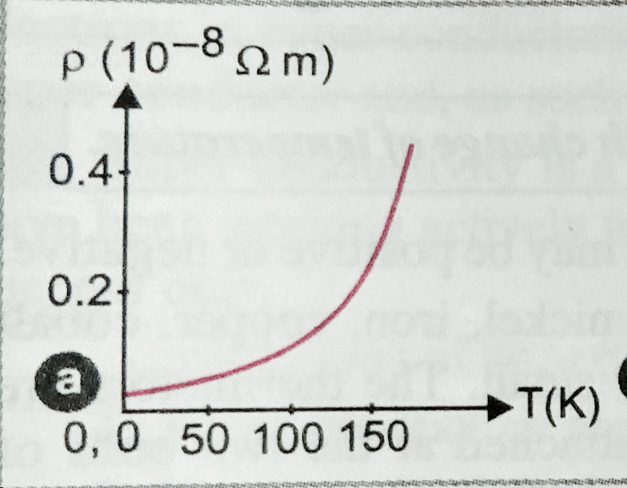
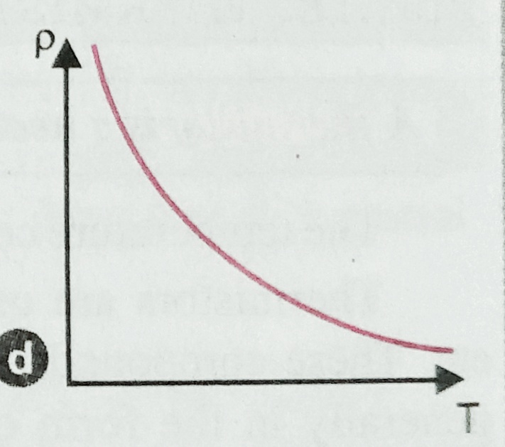
    When we plot the graph resistivity or resistance v/s temperature we get the following plot ;

    (i) For copper (metal )
    (ii) For nickel, iron and chromium  (alloy )


    (iii) For chromium

    (iv) For semiconductor
     

  • Ohm’s law proof and  limitations of Ohm’s law

    Ohm’s law proof and limitations of Ohm’s law

    Ohm’s law proof and limitations of Ohm’s law

    in this topic we will discuss about Ohm’s law proof and limitation of Ohm’s law , in which we will prove Ohm’s law with the help of drift velocity , and graph [V(potential) Vs I(current) ] for non-Ohmic resistance .

    Ohm’s law  and deduction of Ohm’s law –

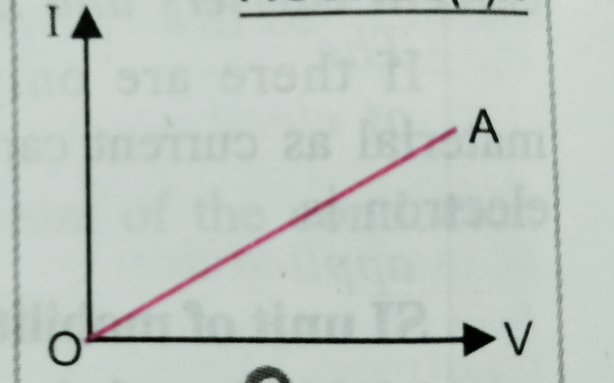
    According to Ohm’s law the current flowing through a conductor is directly proportional to the potential difference applied across the conductor when temperature across the conductor is kept constant .

    i.e potential difference V α current (I)

    or ,  V α I    or,  V = RI   , Where R is the resistance of the conductor which depends on length , shape and nature of the material .

    so , we  can write   R=V/I

    Deduction of Ohm’s law –

    As we know drift velocity Vd = EeƮ/m

    But electric field  E = V/l

    So  Vd = eV Ʈ/ml ……………(i) ,

    We also know that  I = neAVd  therefore Vd = I /neA ……………..(ii)

    From equation (i) and (ii)

                                     eV Ʈ/ml = I /neA

    so , V = Iml/nA e2 Ʈ

    or,  V = I (ml/nA e2 Ʈ) ; here   ml/n Ae2 Ʈ     is constant called resistance

    so,  V = RI

    or , V α I …………………Hence proved Ohm’s law ,

    when we plot the graph potential vs current we get ;


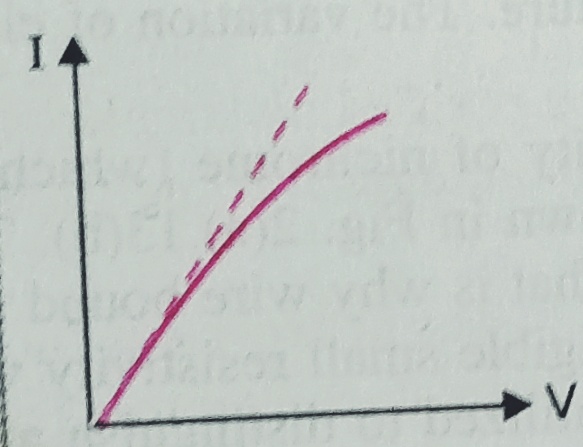
    Limitation of Ohm’s law ( Non-Ohmic devices ) – As  we know when current flows through some conductor heat developed into the conductor , due to which its property like resistivity changes , and its V/I characteristics also changes . Ohm’s law does not discuss about these kind of change .

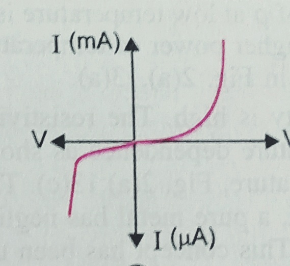
    Those devices which do not obey the Ohm’s law are called non-Ohmic devices .

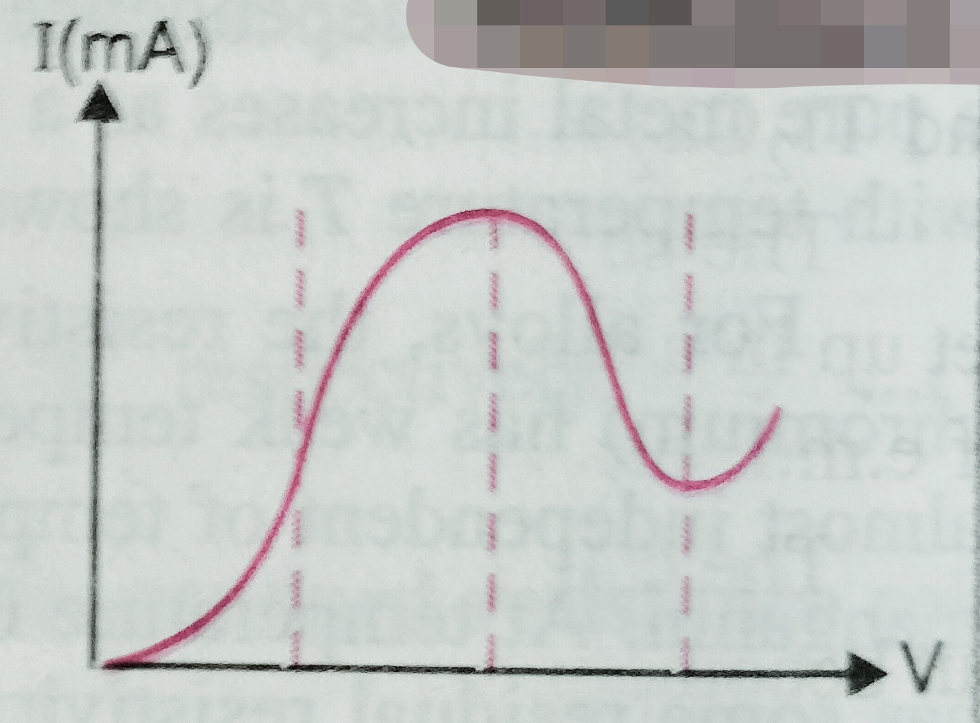
    V-I characteristics of Non- Ohmic materials –

    For junction diode –


    For  Gallium-Arsenide ( GaAs)-

    To know about electrical resistance and resistivity ,and its dependance on the temperature click here-


  • Drift velocity and its relation with current

    Drift velocity and its relation with current

    Drift velocity and its relation with current –

    In this topic we will discuss about drift velocity and how it is related with electric current flowing through a conductor.

    Drift velocity and its relation with current –

    As we know a metal contains large numbers of free electrons . At room temperature these electrons moves randomly into the conductors , and its average velocity becomes zero . But when some potential difference is applied across the ends of the conductor the electric field setup inside it and due to which  electrons drifted from one end to other ( low to high against the direction of electric field ), and drifted electrons suffers several collisions but at the end  reaches to the positive terminal .  So new can define drift velocity is the average velocity with which free electrons drifted from negative to positive terminal under the influence of the external electric field .

    Let V is the potential difference across the end of the conductor , l is the length of the conductor , then , electric field setup E = V/l

    As we know electric field E = F/q = F/e .  Therefore , F= e E = ma , and hence  a= eE /m ;

    SO, drift velocity  Vd = ( v1+v2+v3+………vn)/n ;

    As we know V = u+at  so we can write v1 = u1+at1 , v2 = u2+at2 , v3 = u3+at3 ………………..

    So , Vd= u1+at1 + u2+at2 + u3+at3 ………../n

    =  ( u1+u2+u3…../n ) + a(t1 +t2 +t3 ………../n) ;

    But ( u1+u2+u3…../n ) = 0

    So, Vd = a(t1 +t2 +t3 ………../n) = eE (t1 +t2 +t3 ………..)/mn  .

    But we can write,    a(t1 +t2 +t3 ………../n)=Ʈ

    So, Vd = EeƮ/m ……………………………..eq.


    Relation between current and drift velocity  –     

    Suppose a conductor is of length ‘l’ and area of crossection ‘A’ . Let n is the number density of electron . Then total number of electrons in the conductor = Volume x electron density = A.l.n .

    Total charge  q= A.l.n.e

    Let , V is the potential difference setup across the conductor.

    then , electric field E = V/l

    as we know time Ʈ (t) = l/Vd

    and as we know current I = q/t = Alne/t  = Alne/ (l/Vd) = neAVd

                                     I = neAVd …………….eq. this is the relation between drift velocity and current.

  • Electromotive force (EMF) of the cell

    Electromotive force (EMF) of the cell

    Electromotive force (EMF) of the cell.

    In this topic we will discuss about what is Electromotive force (EMF) of the cell and it is different from potential difference .

    As we know electric current flows through a complete closed circuit ,when there is an source of external force which can bring the ions from low potential to high potential . This external for which makes the current carriers to move in a definite direction called electromotive force (EMF) . In another words we can define ‘ It is the maximum potential difference between two electrodes of the cell when no current flows through the circuits i.e. in open (off) circuit‘ .

    Unit of the EMF is Volt (V) and it is generally represented by ‘E’

    Difference between EMF of a cell and potential difference –

    (i)  EMF -It is related with source of current

    P.D. – It is related with any two points of the closed circuit.

    (ii)  EMF – It cause of potential difference between two point of circuit .

    P.D. – It is an effect .

    (III)  EMF – It is the amount of work done in taking a unit charge once round the complete circuit .

    P.D. – It is the amount of work done to bring unit charge from one point to another point .

    (iv)  EMF – It is equal to sum of potential difference across all components of the circuit ( Including all          the cells connected  in the circuit .

    P.D. – In a closed circuit the different components of the circuit have different potential difference .

    (v)   EMF – It is independent of the external resistance and current drawn from the circuit .

    P.D. – It depends on the resistance between two points of circuit and current flowing through it .

    To know about what is  electric current ? click here-

  • Complete notes of electrostatics

    Complete notes of electrostatics

    Complete notes of electrostatics –

    ELECTROSTATIC POTENTIAL AND CAPACITANCE


    Here complete notes on electrostatics is provided by physics classes by Nayan jha . This notes are based on CBSE  Delhi syllabus . This is the combination of all the topics already provided on this website , which can be studied by the students one by one ( individually )  . If students wants to see all the notes on single page  can go through this page . The link of the all topics are given below –

    Topic-1 -; What is electric charge ? And  what are the properties of charge? 

    Topic-2-; Coulomb’s law of electrostatics (Vector form)

    Topic-3-;  Electric field , and electric field lines . All the properties of electric field lines  

    Topic-4-; Electric dipole , electric field at a point on axial and equatorial point due to dipole .

    Topic-5-;Electric field at any point due to a dipole 

    Topic-6-; Expression for torque and potential energy , when a dipole is placed in external uniform electric field.

    Topic-7-; Electrostatic potential and potential energy

    Topic-8-; Equi-potential surfaces

    Topic-9-; Electric flux and area vector

    Topic-10-; Gauss’s law , proof of Gauss’s law , and prove of Coulomb’s law with the help of Gauss’s law

    Topic-11-; What do you mean by the term electrical capacitance?

    Topic-12-; Explain  parallel plate capacitor , find expression for capacitance of parallel plate capacitor .

    Topic-13-; Grouping (combination ) of capacitors ( series and parallel combination)

    Topic-14-; Energy stored in capacitor and energy density

    Topic-15-;Common potential and loss in energy on shearig charges

    Topic-16-; Non-polar and polar dielectrics

    Topic-17-; Capacitance of parallel plate capacitor with conducting and dielectric slab 


  • Capacitance of parallel plate capacitor with conducting and dielectric slab.

    Capacitance of parallel plate capacitor with conducting and dielectric slab.

    Capacitance of parallel plate capacitor with conducting and dielectric slab.

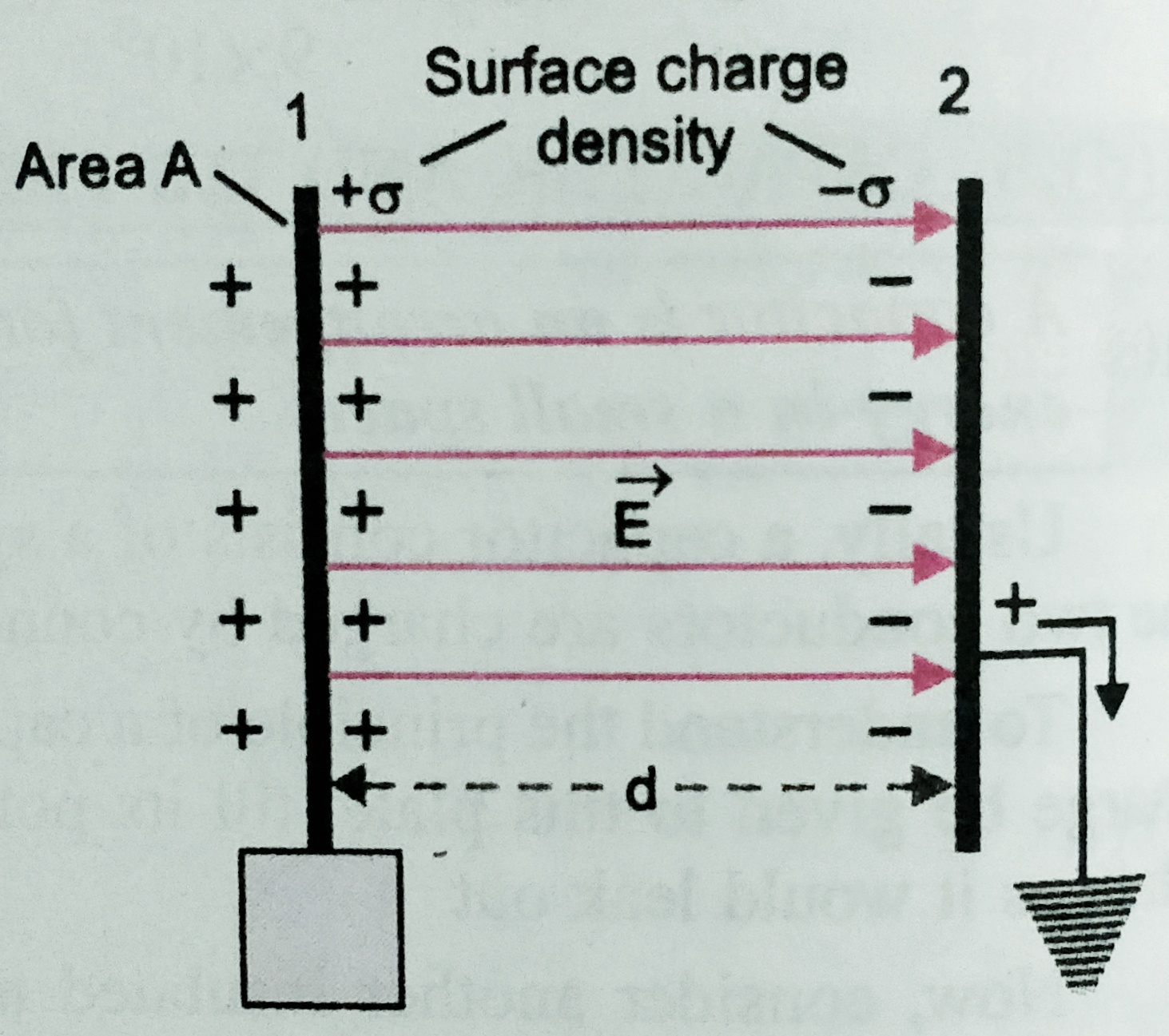
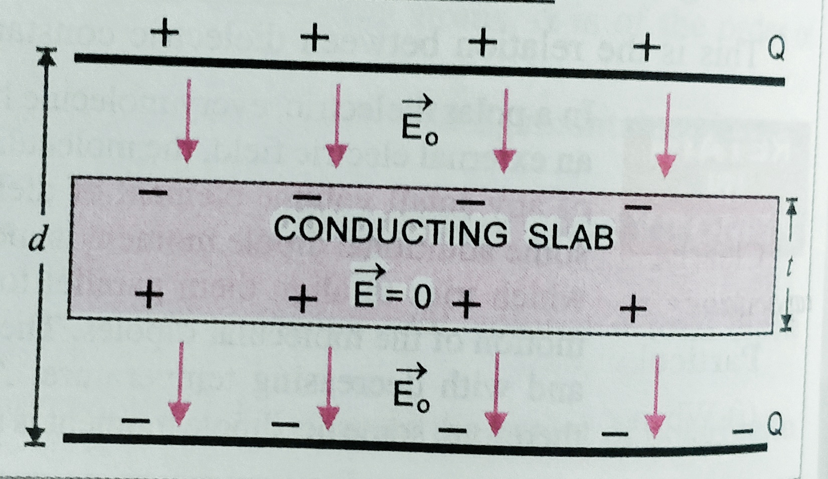
    Capacitance of a parallel plate capacitor with a conducting slab –

    Let A is the area of plates and d is the separation between them is d then capacitance C0= ϵ0A/d .

    Let Q is the charge on the plates of the capacitor. When a conducting slab of thickness ‘t’  ( t< d ) is inserted between the plates . Then the original electric field E0 exist over a distance (d-t) , And inside the metallic plate electric field is zero . so net potential difference between the plates is

    V = E0 (d – t) = σ(d-t)/ϵ0 ;   where σ=Q/A

    As C = Q/V    = Q /( σ(d-t)/ϵ0 ) ;  But , σ = Q/A

    C = Aϵ0 /(d-t) = Aϵ0/[d (1-t/d)] = C0/(1-t/d)

    Special case if    t = d  then   new capacitance of the arrangement will be  infinity ,

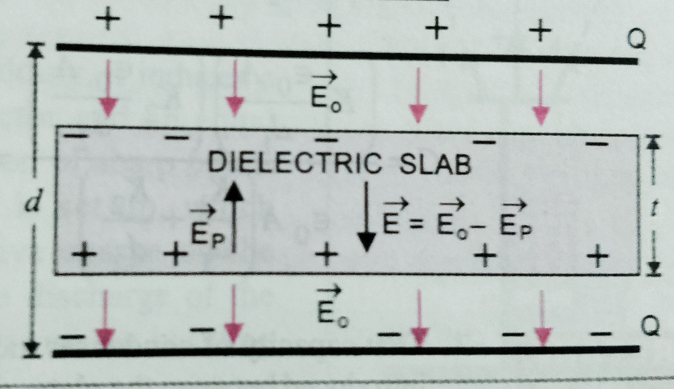
    Capacitance of a parallel plate capacitor with a dielectric slab  –

    Let A is the area of plates and d is the separation between them is d then capacitance C0= ϵ0A/d .

    Let Q is the charge on the plates of the capacitor. When a dielectric slab of thickness ‘t’  ( t< d ) , and dielectric constant K  is inserted between the plates . Then the original electric field E0 exist over a distance (d-t) , And inside the dielectric plate electric field is E0/K . So net potential difference between the plates is ,

    V = E0 (d – t) +( E0 t/K)  = E0[d-t+(t/K)]

    = σ[d-t+(t/K)] /ϵ0  ,   where σ=Q/A

    As C = Q/V    = Q / σ[d-t+(t/K)] /ϵ0  ;  But , σ = Q/A

    C = Aϵ0 /(d-t +t/K)= Aϵ0/[d (1-t/d+t/dK)] = C0/(1-t/d  +t/dK) ;

    If t= d   then  new capacitance  C = KC0


    *** Special cases –

    When a dielectric  slab of dielectric constant ( K ) is inserted between the plates having same thickness of separation between the plates . (t = d ) . 


    When battery disconnected             

    ( I ) Capacitance C = KC0

    (II) Potential  V =  V0/K

    (III) Charge  Q = Q0

    (iv) potential energy U = U0/K

      When battery remain connected       

    (I) Capacitance C = K C0

    (II) Potential  V = V0

    (III)  Charge   Q = K Q0

    (IV)  potential energy  U = KU0