Tag: electromagnetic induction and alternating current

  • Test magnetism and electromagnetic induction

    There are 20 questions in the question paper , in which 14 are objective, (1 marker) and other 6 are subjective which carry 2 marks each .

    This question paper covers the chapter magnetism and electromagnetic induction . It is just for the practice the questions of the chapters magnetism and electromagnetic induction.

    1. Define the term magnetic moment of a current loop . Write the expression for the magnetic moment when an electron revolve at speed v around the   orbit of radius r in hydrogen atom .

     2 .  Define magnetic susceptibility of the materials . Name two elements , one having positive and other having negative susceptibility . what does negative susceptibility signify ?

      3. A bar magnet of magnetic moment M is aligned parallel to the direction of a uniform magnetic field B. What is the work done to turn the magnet, so as the align its magnetic moment  (i) Opposite to the field direction  (ii) Normal to the field direction?

    4. Two circular coils one of small radius r and other of very large radius R are placed coaxially with center coinciding. Obtain the mutual inductance of the arrangement.

    To download the complete question paper click here –
  • Objective questions of alternating current

    Objective questions of alternating current

    Objective questions of alternating current

    LC-OSCILLATOR

    This assignment (Objective questions of alternating current),provide the important objective questions of the chapter alternating current ,which is important for the students preparing for class-12th board examination or , other competitive examinations (JEE/NEET)

    Before to solve this assignment (Objective questions of alternating current), student should solve the assignment of objective questions of electromagnetic induction-

    1. A direct current of 5 amp is superimposed on an alternating current I = 10sin ɷt flowing through a wire. The effective value of the resulting current will be:
    • (a)(15/2) amp     (b) 5√3 amp  (c) 5√5 amp      (d) 15 amp
    1. In an AC circuit, a resistance of R ohm is connected in series with an inductance L. If phase angle between voltage and current is 45°, the value of inductive reactance will be:
    • (a)R/4
    • (b)R/2
    • (c)R
    • (d)cannot be found with the given data
    1. Resonance frequency of L – C circuit is:
    • (a)1/2π √LC       (b) 1/2πLC   (c) 1/2π √L/C   (d) 1/2π √LC
    1. In L-C-R series AC circuit, the phase angle between current and voltage is:
    • (a)any angle between 0 and ± π/2
    • (b)π/2
    • (c)π
    • (d)any angle between 0 and π
    1. In an L-C-R circuit, the capacitance is made one-fourth, when in resonance, so that the circuit remains in resonance?
    • (a)4 times    (b) (1/4) times       (c) 8 times        (d) 2 times

    TO download complete assignment of Objective questions of alternating Current- click here-

  • Objective questions of electromagnetic induction

    Objective questions of electromagnetic induction

    Objective questions of electromagnetic induction-

    This assignment contains Objective questions of electromagnetic induction, which will help the students to prepare for class 12th board examination and other competitive exams like JEE/NEET.

    Before to solve this assignment students has to solve assignment of magnetic effect of current, to solve the questions of magnetic effect of current click here

    1. Lenz’s law is a consequence of the law of conservation of:
    • (a)charge      (b) mass     (c) momentum      (d) energy
    1. The law of electromagnetic induction have been used in the construction of a:
    • (a)galvanometer (b) voltmeter    (c) electric motor   (d) generator
    1. A cylindrical bar magnet is kept along the axis of a circular coil. On rotating the magnet about the axis, the coil will have induced in it:
    • (a)a current (b) no current       (c) only an em        (d) both an emf and a current
    1. A horizontal straight conductor when placed along south-north direction falls under gravity; there is:
    • (a)an induced current from south to north direction
    • (b)an induced current from north to south direction
    • (c)no induced emf along the length of the conductor
    • (d)an induced emf along the length of the conductor
    1. A car moves on a plane road. Induced emf produced across the axle is maximum when it moves:
    • (a)at the poles (b)moves at equator (c) remains stationary
    • (d) no emf is induced at all

    To download complete assignment of objective questions of electromagnetic induction click here-Electromagnetic Induction

    after solving this assignment of objective questions of electromagnetic induction student should solve the assignment of objective questions of alternating current . To download the complete assignment of objective questions of alternating current click here –

  • LC-oscillation

    LC-oscillation

    OSCILLATION IN AN LC – CIRCUIT

    LC- oscillation —-

    An LC circuit consists  an inductor and a capacitor connected in parallel . Its another name is tank circuit.

    Working –

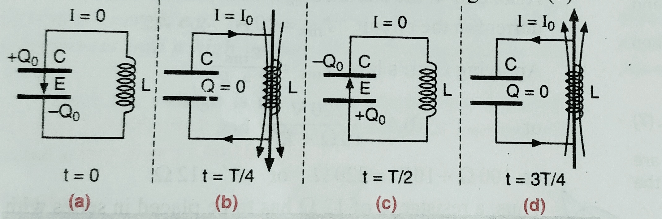
     At t= 0 – – capacitor is first charged . The whole energy is stored in the capacitor which is U= ½ CV2 , at that instant charge on the capacitor is Q , and there is no current through the circuit and energy in the inductor at that instant is zero .

     Watch Important Physics Videos 

    At t=T/4 (T= time period of oscillation ) –  –  the capacitor begins to discharge and a  growing current starts flowing through the inductor , which setup magnetic field around it which produces induced current in the inductor  in opposite direction  and hence there is delay in discharge . As the capacitor discharges its energy starts decreasing which converted as magnetic energy in the inductor , and at an instant total charge in capacitor is zero , and hence energy stored in the capacitor is zero and energy stored in the inductor at that time is ½ LI2‑.

    At t=T/2 – as soon as capacitor is completely discharged , the magnetic field around the inductor starts decreasing , it produced an induced emf in opposite direction  , due to which capacitor start charging it self in opposite direction and at an instant inductor discharged completely and capacitor charged completely again which is ½ CV2 .

    This process repeated again and again then energy obtained once keep on oscillating between capacitor and inductor and to and fro pulses of current are produced .

    LC-OSCILLATOR
    LC-OSCILLATOR

     WORKING OF LC-OSCILLATION AND DERIVATION OF ITS FREQUENCY – Watch Video Below

    Derivation for frequency of LC- oscillation

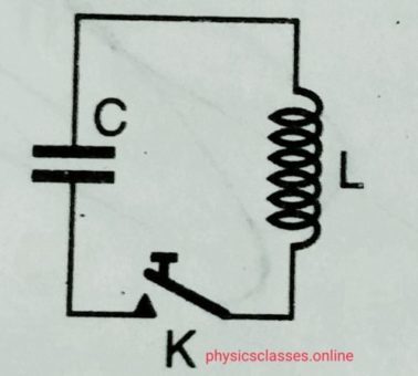
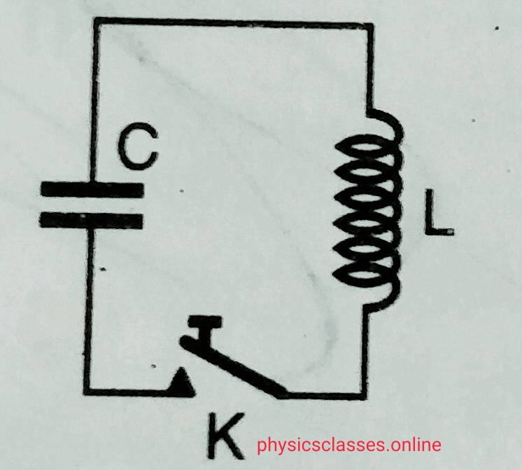
    – Suppose an electrical circuit having a capacitor of capacitance C and an inductor of inductance L connected as shown in fog. Below-

    LC OSCILLATION
    LC OSCILLATION

    . Let the capacitor is charged Q initially and when key is closed emf induced in the inductor is L (di / dt) and potential difference across the capacitor is Q/C . Then from Kirchhoff’s law    L (dI/dt) +Q/C =0 ………..(i)

    But I = dQ /dt

    And hence eq. (i) may be written as

    L(d2Q/dt2)+ Q/C =0

    Or , d2Q/dt2 + Q/LC = 0 ………………………..(ii)

    But as we know eq . of SHM.  May be written as  d2x/dt2+ ω2x = 0  ………..(iii)

    Comparing eq. (ii) and (iii) we get

    ω2 = 1/LC

    or,  ω= 1/√LC .

    but ,   ω=2Πѵ ( where ѵ=frequency)

    so ,  frequency ,  ѵ= 1/2Π√LC


  • PHASOR DIAGRAM

    PHASOR DIAGRAM

    PHASOR DIAGRAM-

    PHASORS AND PHASOR DIAGRAM-

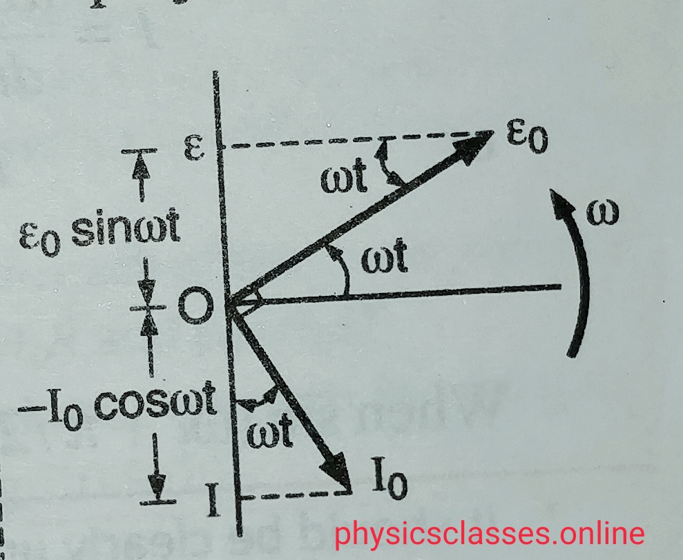
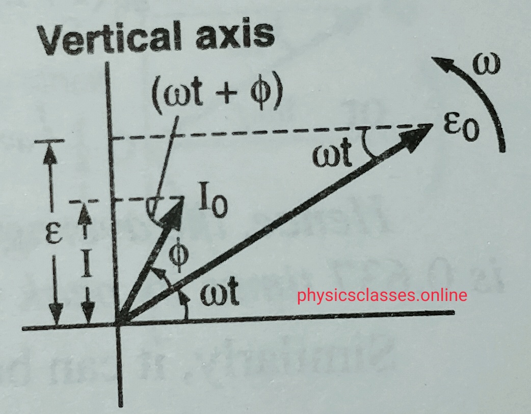
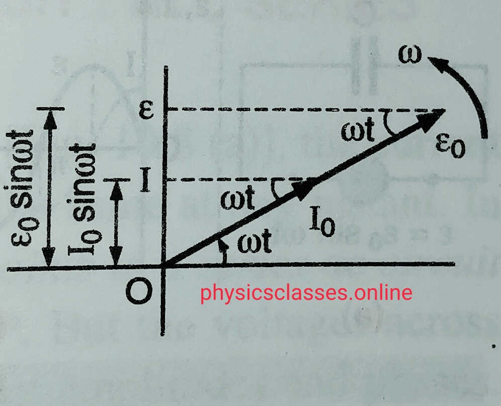
    The co-planar vectors which represents sinusoidal time varying quantities like alternating current or alternating voltage are known as phasor and the graphical representation of these quantities for the ac circuit is known as phasor diagram.

    In another words we can say when AC or alternating voltage  represented as rotating vectors in a graph is  known as phasor diagram .

    • Phasors are represented by the arrows rotating anticlockwise .
    • The length of the arrow represent the peak current or peak voltage.
    • Phasor diagram represents the phase relation between alternating current and voltage

    Representation of phasor diagram for an ac source-

    PHASOR DIAGRAM1
    PHASOR DIAGRAM-1


    Phasor diagram when ac circuit containing only resistance –

    PHASOR DIAGRAM -2
    PHASOR DIAGRAM -2

     Phasor diagram when ac circuit containing only capacitor-

    PHASOR DIAGRAM -3
    PHASOR DIAGRAM -3


    Phasor diagram when ac circuit containing only inductor-

    PHASOR DIAGRAM -4
    PHASOR DIAGRAM -4


  • MUTUAL INDUCTANCE OF TWO COAXIAL SOLENOID

    MUTUAL INDUCTANCE OF TWO COAXIAL SOLENOID

    MUTUAL INDUCTANCE OF TWO COAXIAL SOLENOID

    In this topic we will derive the expression for coefficient of mutual induction or mutual inductance of two coaxial solenoid

    MUTUAL INDUCTION OF TWO COAXIAL SOLENOID–

    mutual induction
    mutual induction fig.-

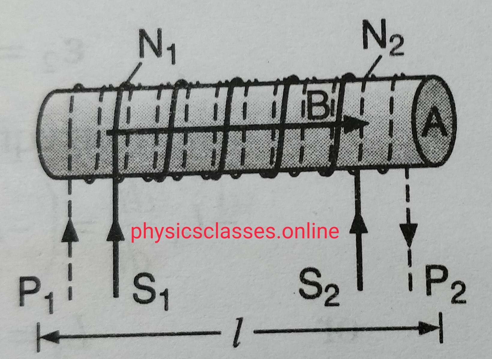
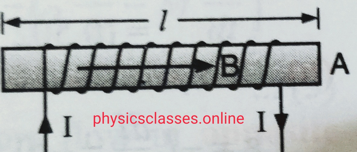
    Let us consider two coaxial solenoid P1P2 and S1S2 (as shown in figure).

    Let their common length is ‘l’ with cross-sectional area  A  and having N1 turns  but second coil has N2 turns .

    If I1 is the current flows through the coil P1P2 , the magnetic field at its centre ,  B = µ0 n1 I . so magnetic flux linked with the coil S1S2 = B A .

    Magnetic flux for entire coil S1S2 , ɸ = BAN2 = µ0n1n2 A I = µ0 N1N2 I A/ l …………(i)

    But as we know , ɸ= MI ……………….(ii) (Here M is the mutual induction of the coil)

    From eq. (i) and (ii)

    MI = µ0 N1N2 I A / l

    So  M= µ0 N1N2  A/l .


    Points to be remember-

    • If a medium of relative permeability µr fills the entire space in the inner solenoid then mutual induction M= µ0µr N1N2  A/l
    • If the cross-sectional area of both the the coils are different then we always consider the inner coil radius ( area of that coil having smaller area of cross-section)
    • The calculation of mutual induction is quite complicated even in the case of considerable symmetry.
  • MUTUAL INDUCTION

    MUTUAL INDUCTION

    Mutual induction-

    In this topic students will study what is mutual induction and coefficient of mutual induction / mutual inductance? And what is the unit of mutual inductance

    mutual induction
    mutual induction

    Mutual induction-

    Let us consider two coils placed near to each other closely . One of the coil carries the battery is the primary coil and the other one is secondary coil connected with a galvanometer. When current starting flows through the primary coil  then its value increases from zero value to a fixed value during this time we observe that there is some deflection in the galvanometer . as we know when current passes through a coil (solenoid ) magnetic field setup ,due to increasing value of current magnetic field through the coil also increases and hence magnetic flux linked with the secondary  coil also increases , and according to Faraday’s law  emf  setup across the secondary coil .

    So we can say , The phenomena of inducing current in a circuit by changing the current in a neighbouring circuit is called mutual induction. We can also define it the property of two circuits by virtue of which each circuit opposes any change in flux or strength of current flowing through other circuit.

    It is found that the flux ‘ɸ’ linked with the secondary coil is directly proportional to the current ‘I’ flowing through the primary coil ,

    i.e.      ɸ = I

    or         ɸ = MI ( M is a constant called coefficient of mutual induction , the value of M depends upon the characteristics of the circuit ant their orientations . )

    so,     M = ɸ/I   ; if  I =1 ampere then M=ɸ

    So we can define coefficient of mutual induction is equal to the flux linked with the coil when unit current passes through the another coil.

    We know that,  emf ‘e’ = -dɸ/dt =  – d(MI)/dt  =  -M dI/dt  ,

    If dI/dt = 1 then , m  = – e , so we can define coefficient of mutual induction is equal to emf induced in secondary coil when rate of change of secondary coil is unity.

    Unit of mutual inductance  is Henry (H) , Henry is also the unit of self inductance  , we can define that mutual induction of two circuit is said to be 1 Henry if a current changing at the rate of 1 ampere per second  in one circuit and induces 1 volt of emf in other circuit.

     To derive the expression for the mutual induction of two coaxial solenoid click here

    To derive the expression for  the coefficient of self induction click here

  • SELF-INDUCTION OF LONG SOLENOID

    SELF-INDUCTION OF LONG SOLENOID

    SELF-INDUCTION OF LONG SOLENOID

    self- induction
    self- induction of long solenoid

    SELF-INDUCTION OF LONG SOLENOID this topic is important for the class 12th board examination

    Self-inductance of long air-cored solenoid question may asked as –

    what do you mean by the term self-induction ? Find expression for the self-inductance of long air cored solenoid .

    Self-inductance of long air-cored solenoid –

    Suppose a long air cored solenoid having ‘n’ number of turns per unit length . If current in the solenoid is ‘I’  the magnetic field within the solenoid B= µ0nI . If A is the area of cross-section of the solenoid , the effective flux linked with the solenoid of length ‘l’ ; ɸ=NBA……………………………….(i)

    where N is the total no. of turns of the solenoid . so ɸ= n l B A …………………………………….(ii) . substituting the value of B in this equation

    we get,

    ɸ =n l(µ0nI ) A  = µ0n2A l I .

    so , self-inductance  of solenoid L=ɸ/ I.=   µ0n2A l I / I  = µ0 n2 Al

    but n= N/l

    so self- inductance L= µ0 N2A/ l .

    If solenoid contains a core of ferromagnetic material , having relative permeability µr then self-inductance  L=   µ0µr N2A/ l .

    necessary picture of this topic  is shown above**.

  • SELF-INDUCTION

    SELF-INDUCTION

    Explain the term self-induction of a coil

    Self – Induction –

    It is the property of an electric circuit or coil by virtue of which it opposes any change of flux or current in it by inducing a current in itself is called self- induction. In another words we can say “self-induction is the inertia of electricity “. Due to self -induction an electric circuit resist any change of current through it .

    As we know magnetic flux linked with a coil is directly proportional to the current flowing through the circuit

    i.e.    ɸ α I ( ɸ= flux linked with the coil, and I is the current in the circuit )

    ɸ = LI ( L is the constant called coefficient of self- induction or self-inductance  or only inductance . )

    If current I =  1 ampere, then flux ɸ= L  . so we can define self-induction is the flux linked with the coil when unit current passes through the coil.

    as we know,

    emf  e= – dɸ/dt

    e= -d (LI)/ dt

    e= -L ( dI/dt)

    L= –  e/(dI/dt)

    So we can define self-inductance of a circuit is numerically equal to the induced emf setup in it when the rate of change of current through it is unity.

    Unit of self-inductance is Henry (H) .  We can define self-inductance of a coil is one Henry if 1 volt emf induced in the coil when rate of change of current through the coil is unity.

    To find the expression for self-inductance of long solenoid click here

  • Faraday’s law of electromagnetic induction

    Faraday’s law of electromagnetic induction

    Faraday’s law of electromagnetic induction

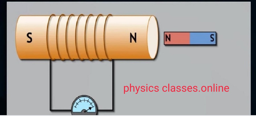
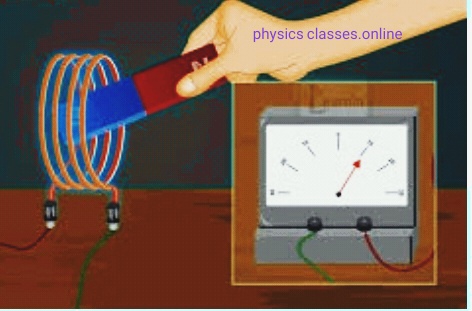
    Electromagnetic induction – As we know when electric current passes through a conductor then magnetic field developed across the conductor , first discovered by Oersted . But Michael Faraday found its converse is also possible i.e. Whenever magnetic field changes around a coil ( and hence magnetic flux linked  across the coil changes  ) electric current induced in the coil , such phenomena is called electromagnetic induction (E.M.I.) . And the current induced in the coil  is known as induced current and emf developed is known as induced emf .

    Faraday's law of EMI
    Faraday’s law of EMI

    Faraday’s laws of electromagnetic induction – On the basis of experiments Faraday’s gave the two laws –

    (i) Whenever electric flux linked with the coil changes then emf induced in the coil . The emf lasts only for the time for which flux is changing .

    (ii)  The magnitude of induced emf is directly proportional to rate of change of magnetic flux linked with the coil.   I.e.  emf   e  α ɸ2 – ɸ1 / t (time taken).

    Or  e =  – k dɸ/ dt . ( Here negative sign shows the  induced emf oppose any change in the magnetic flux through the coil.

    After combining these two equations Faraday’s law states “ An induced emf is produced in any closed circuit if there is a varying magnetic flux . the magnitude of induced emf  is equal to the negative of the time rate change of magnetic flux through the circuit .”