Author: Nayan Jha

  • Practical chemistry for class 8/9/10th

    Practical chemistry for class 8/9/10th

    Practical chemistry for class 8/9/10th –

    Here physics classes by Nayan jha provide Practical chemistry for class 8/9/10th  whish is prepared by Rahul jha [Currently working with the St. Joseph School , Bhagalpur ( Bihar) , He is also the co-founder of QT classes bhagalpur  ] .

    What is electric charge ? and what are the properties of charge? To know -click here-

    These practical is totally based on ICSE/CBSE/ALL STATES BOARD .

    With the help of these notes, Practical chemistry for class 8/9/10th students can prepare the notes for their chemistry practical for their class examinations .

    S.No.                                            Name of the Experiment page
    1. To Identify HYDROGEN Gas 2
    2. To Identify OXYGEN Gas 3
    3. To Identify CARBON DIOXIDE  Gas 4
    4. To Identify SULPHER DIOXIDE  Gas 5
    5. To Identify HYDROGEN CHLORIDE  Gas 6
    6. To Identify AMMONIA Gas 7
    7. To Identify NITROGEN DIOXIDE Gas 8
    8. To Identify CHLORINE Gas 9
    9. To Identify HYDROGEN SULPHIDE Gas 10
    10. To Identify WATER VAPOUR

    (Experiments by Heating in a dry test tube)

    11


     What is electric current? to know  complete explanation about it -click here-


     Experiment No. 1


    Name of the Experiment : To Identify Hydrogen gas

    No.           Experiment    Observation        Inference
    1 On zinc pieces few drops of dilute sulphuric acid is added A colourless, adourless, gas comes out Gas may be hydrogen
    2 Moist red and blue litmus paper are brought near the mouth of test tube There is no change Gas is neutral in nature
    3 A glowing Matchstick is brought Near the mouth of the  test tube It is put off with a pop sound Gas is hydrogen


    Reaction :   Zn+ H2SO4→Zn SO4+H2


    What is electric charge ? To know abot it click here-

    Experiment No. : 2


    Name of the Experiment : To Identify Oxygen gas

    S.No. Experiment Observation Inference
    1. Sodium Nitrate is heated strongly Colourless, odourless gas comes out Gas may be oxygen
    2. Moist blue and red litmus paper is brought near the mouth of the test tube There is no change Gas is neutral in nature
    3. A glowing splinter is brought near the mouth of the test tube It glows more brightly Gas is oxygen


    Reaction: 2NaNO3    2Na NO2+O2


    Experiment No. : 3


    Name of the Experiment : To Identify Carbon Dioxide gas

    S.No. Experiment Observation Inference
    1. To the aqueous solution of sodium carbonate few drops of dil. Sulphuric acid is added Brisk effervescence is seen and a colourless, odourless gas comes out Gas may be carbon dioxide
    2. Moist blue and red litmus paper is brought near the test tube It turns red Gas is acidic in nature
    3. Gas is passed through lime water It turns milky Gas may be carbon dioxide
    4. An acidified potassium dichromate paper is brought near the mouth of the test tube There is no change Gas is carbon dioxide


    Reaction  :  Na2CO3+H2SO4     →      Na2SO4+H20+CO2


    Experiment No. 4


    Name of the Experiment : To Identify Sulphur Dioxide gas

    S.No. Experiment Observation Inference
    1. To the aqueous solution of sodium sulphite few drops of dil. Sulphuric acid is added A colourless gas with a pungent smell of burning sulphur comes out Gas may be sulphur dioxide
    2. A blue litmus paper is brought near the mouth of the test tube It turns red Gas is acidic in nature
    3. Gas is passed through lime water It turns milky Gas may be carbon dioxide or sulphur dioxide
    4. An acidified potassium dichromate paper is brought near the mouth of the test tube It turns green Gas is sulphur dioxide


    Reaction :Na2SO3+H2SO4→Na2SO4+H2O+SO2


    Experiment No. 5


    Name of the Experiment : To Identify Hydrogen chloride gas

    S.No. Experiment Observation Inference
    1. Sodium chloride is heated with concentrated sulphuric acid A colourless gas with a chocking odour comes out Gas may be hydrogen chloride
    2. Moist blue and red litmus paper is brought near the mouth of the test tube It turns red Gas is acidic in nature
    3. A glass rod dipped in concentrated ammonium hydroxide is brought near the mouth of the test tube Dense white fumes are seen Gas is Hydrogen chloride


    Reaction : NaCl +H2SO4   NaHSO4+HCl


    Experiment No. 6


    Name of the Experiment : To Identify Ammonia gas

    S.No. Experiment Observation Inference
    1. Ammonium chloride is gently warmed with sodium hydroxide A colourless gas with a strong pungent smell comes out Gas may be ammonia
    2. A moist red  litmus paper is brought near the mouth of the test tube It turns blue Gas is basic in nature
    3. A glass rod  dipped in concentrated hydrochloric acid is brought near the mouth of the test tube Dense white fumes are seen Gas is ammonia
    4. A cotton wool soaked in Nessler’s reagent is brought near the mouth of the test tube It turns deep brown Gas is ammonia


    Reaction: NH4Cl +NaOH → NaCl +H2O +NH3


    Experiment No. : 7


    Name of the Experiment : To Identify Nitrogen Dioxide gas

    S.No. Experiment Observation Inference
    1. Copper turnings are heated Concentrated nitric acid Reddish brown colour gas comes out Gas may be Nitrogen dioxide
    2. A moist blue litmus paper is brought near the mouth of the test tube It turns red Gas is acidic in nature
    3. A starch iodide paper is brought near the mouth of the test tube It turns blue-black Gas is nitrogen dioxide
    4. Potassium iodide paper is brought near the mouth of the test tube It turns deep brown Gas is Nitrogen dioxide


    Reaction : Cu + 4HNO3        Cu(NO3)2+ 2H2O +2NO2


    Experiment No. : 8


    Name of the Experiment : To Identify Chlorine  gas

    S.No. Experiment Observation Inference
    1. A mixture of hydrogen chloride and manganese IV oxide is heated in a hard glass test tube with concentrated sulphuric acid A greenish yellow colour gas comes out Gas may be Chlorine
    2. A moist blue litmus paper is brought near the mouth of the test tube First it turns deep brown and then bleached Gas is chlorine
    3. A starch iodide paper is brought near the mouth of the test tube It turns blue-black Gas is chlorine


    Reaction : 2NaCl +3H2SO4+ MnO2  2NaHSO4 +MnSO4 + 2H2O+ Cl2


    Experiment No. : 9


    Name of the Experiment : To Identify Hydrogen Sulphide gas

    S.No. Experiment Observation Inference
    1. The aqueous solution of sodium sulphide few drops of dilute sulphuric acid is added A colourless gas with the smell of rotten egg comes out Gas may be hydrogen sulphide
    2. A filter  paper is dipped in red lead acetate and brought near the mouth of the test tube It turns silvery-black Gas is hydrogen sulphide gas


    Reaction : Na2S + H2SO4 → Na2SO4 +H2S


    Experiment No. : 10


    Name of the Experiment : To Identify Water Vapour

    S.No. Experiment Observation Inference
    1. Blue crystals of copper sulphate is heated in a dry test tube A colourless, odourless, gas comes out and condenses on the colour part of the test tube form droplets of colourless liquid Liquid may be water
    2. A moist blue and red litmus paper is brought near the mouth of the test tube There is no change Liquid is neutral in nature


    3 Few drops of the colourless liquid is added to anhydrous copper II sulphate The white powder turns deep blue The residue or liquid is water


    Reaction : CuSO4. 5H2O             CuSO4 +5H2O

          Blue crystalline solid                 White anhydrous powder


     Rest practicals will be uploaded soon . 

     Are you scared of physics . to know how to improve your interest in physics- click here-


  • Complete notes of electrostatics

    Complete notes of electrostatics

    Complete notes of electrostatics –

    ELECTROSTATIC POTENTIAL AND CAPACITANCE


    Here complete notes on electrostatics is provided by physics classes by Nayan jha . This notes are based on CBSE  Delhi syllabus . This is the combination of all the topics already provided on this website , which can be studied by the students one by one ( individually )  . If students wants to see all the notes on single page  can go through this page . The link of the all topics are given below –

    Topic-1 -; What is electric charge ? And  what are the properties of charge? 

    Topic-2-; Coulomb’s law of electrostatics (Vector form)

    Topic-3-;  Electric field , and electric field lines . All the properties of electric field lines  

    Topic-4-; Electric dipole , electric field at a point on axial and equatorial point due to dipole .

    Topic-5-;Electric field at any point due to a dipole 

    Topic-6-; Expression for torque and potential energy , when a dipole is placed in external uniform electric field.

    Topic-7-; Electrostatic potential and potential energy

    Topic-8-; Equi-potential surfaces

    Topic-9-; Electric flux and area vector

    Topic-10-; Gauss’s law , proof of Gauss’s law , and prove of Coulomb’s law with the help of Gauss’s law

    Topic-11-; What do you mean by the term electrical capacitance?

    Topic-12-; Explain  parallel plate capacitor , find expression for capacitance of parallel plate capacitor .

    Topic-13-; Grouping (combination ) of capacitors ( series and parallel combination)

    Topic-14-; Energy stored in capacitor and energy density

    Topic-15-;Common potential and loss in energy on shearig charges

    Topic-16-; Non-polar and polar dielectrics

    Topic-17-; Capacitance of parallel plate capacitor with conducting and dielectric slab 


  • Capacitance of parallel plate capacitor with conducting and dielectric slab.

    Capacitance of parallel plate capacitor with conducting and dielectric slab.

    Capacitance of parallel plate capacitor with conducting and dielectric slab.

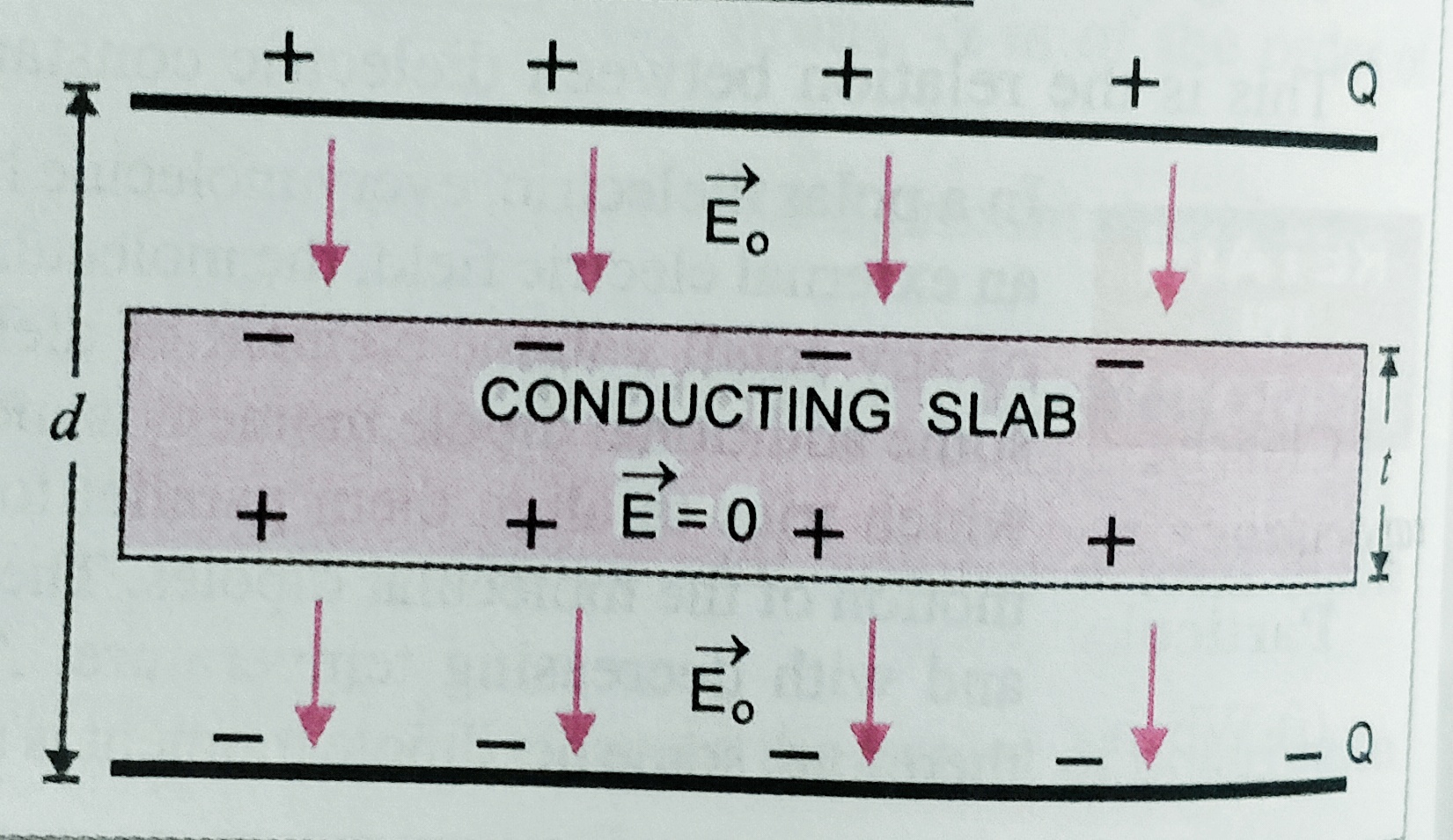
    Capacitance of a parallel plate capacitor with a conducting slab –

    Let A is the area of plates and d is the separation between them is d then capacitance C0= ϵ0A/d .

    Let Q is the charge on the plates of the capacitor. When a conducting slab of thickness ‘t’  ( t< d ) is inserted between the plates . Then the original electric field E0 exist over a distance (d-t) , And inside the metallic plate electric field is zero . so net potential difference between the plates is

    V = E0 (d – t) = σ(d-t)/ϵ0 ;   where σ=Q/A

    As C = Q/V    = Q /( σ(d-t)/ϵ0 ) ;  But , σ = Q/A

    C = Aϵ0 /(d-t) = Aϵ0/[d (1-t/d)] = C0/(1-t/d)

    Special case if    t = d  then   new capacitance of the arrangement will be  infinity ,

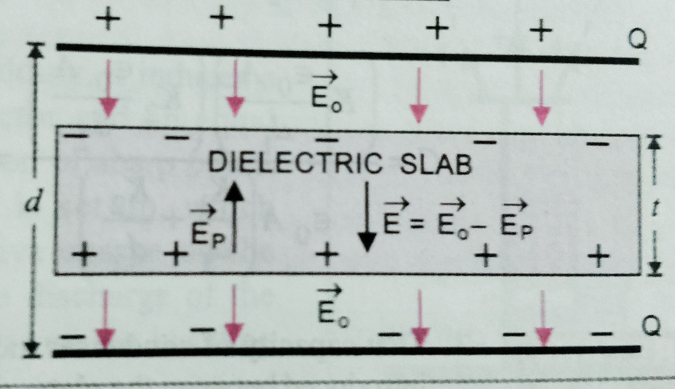
    Capacitance of a parallel plate capacitor with a dielectric slab  –

    Let A is the area of plates and d is the separation between them is d then capacitance C0= ϵ0A/d .

    Let Q is the charge on the plates of the capacitor. When a dielectric slab of thickness ‘t’  ( t< d ) , and dielectric constant K  is inserted between the plates . Then the original electric field E0 exist over a distance (d-t) , And inside the dielectric plate electric field is E0/K . So net potential difference between the plates is ,

    V = E0 (d – t) +( E0 t/K)  = E0[d-t+(t/K)]

    = σ[d-t+(t/K)] /ϵ0  ,   where σ=Q/A

    As C = Q/V    = Q / σ[d-t+(t/K)] /ϵ0  ;  But , σ = Q/A

    C = Aϵ0 /(d-t +t/K)= Aϵ0/[d (1-t/d+t/dK)] = C0/(1-t/d  +t/dK) ;

    If t= d   then  new capacitance  C = KC0


    *** Special cases –

    When a dielectric  slab of dielectric constant ( K ) is inserted between the plates having same thickness of separation between the plates . (t = d ) . 


    When battery disconnected             

    ( I ) Capacitance C = KC0

    (II) Potential  V =  V0/K

    (III) Charge  Q = Q0

    (iv) potential energy U = U0/K

      When battery remain connected       

    (I) Capacitance C = K C0

    (II) Potential  V = V0

    (III)  Charge   Q = K Q0

    (IV)  potential energy  U = KU0


  • Non-polar and polar dielectrics

    Non-polar and polar dielectrics

    Non-polar and polar dielectrics –

    In this topic we will discuss about Non-polar and polar dielectrics and dielectric polarization with electrical susceptibility.

    Non polar and polar dielectrics  –

    As we know the dielectrics are insulating material which transmit electric effect without conducting electricity .

    Dielectrics is of two types , Non-polar Dielectrics and polar Dielectrics .

    In non-polar dielectric ,  in the molecule of the dielectric the centre of mass of the positive charge coincide with the centre of mass of the negative charge . Like , Hydrogen , nitrogen , oxygen , carbon dioxide , methane , benzene etc . In such kind of molecule each molecule has zero dipole moment and they are symmetric in shape .

    But in case of polar dielectric . The  centre of mass of positive and negative charges do not coincide  because of the asymmetric shape of the molecules. It has permanent dipole moment . example – HCl , NH3 H2O, alcohol etc .

    Dielectric polarization –

    When a non polar dielectric is held in external electric field , the two centres of positive and negative charges in the molecules are separated . The molecules gets distorted and is said to be polarized as a small dipole moment .

    The dipole moment acquired is given as , p = αϵ0E0  Where α is the constant of proportionality called molecular polarizability .  Its unit is m3 .

    If N is the number of atoms per unit volume then , electric polarization P = N p   or,  P = N qx .

    Its unit is C-m-2

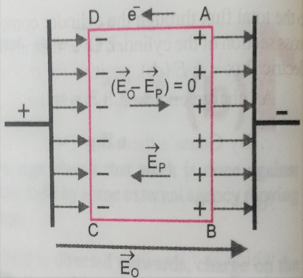
    If we consider a small volume element in the interior of the slab  as shown in figure . , each volume has no net charge ,though it has net dipole moment . This is because positive charge of each dipole sits close to the negative charge of the adjacent dipole . . The negative end of the dipole remain un-neutralized  at the surface AB and positive end of the dipole at CD . then the effective electric field E = E0 -EP  ;

    Further EP = σ/ϵ =  p/ϵ.

    Electric susceptibility –  As we know that the electric polarization P αE    or, p= ϵ  χ E

    Where  χ is constant called electrical susceptibility .

    For vacuum χ = 0 ;

    But as we know ,   E = E0 -EP  = E0 – P/ϵ = E0  –  ϵ  χ E/ϵ

    Or , E = E0 -χE  ;

    E0 = E  +   χ E  = E( 1+ χ )

    OR ,             E0/E  =  1 + χ

    K ( Dielectric constant or relative permittivity ) = 1 + χ   [ since  K= E0/E  ]

    K (ϵr) = 1 +  χ …………………This is the relation between relative permittivity and susceptibility .

  • Common potential and loss in energy on shearing charges .

    Common potential and loss in energy on shearing charges .

    Common potential and loss in energy on shearing charges .

    Before to know about the topic Common potential and loss in energy on shearing charges .student must have to know about Energy stored in the capacitor and electrostatic potential .

    To know about energy stored in a capacitor click here-

    To know about the electrostatic potential energy click here- 

    In this topic students will know about Common potential and loss in energy on shearing charges . its derivation and numerical is important for class 12th ( Board examination) and for NEET/JEE examinations .

    Common potential – When two charged capacitors are connected with each other using a conducting wire then charge starts flowing from high potential to low potential, and after some time their potential becomes equal.

    Let two capacitors C1 and C2 and their potentials are V1 And V2 respectively. Then total charge before combination Q = C1V1 + C2V2.

    Let they are connected with a conducting wire, then charge start flowing from high potential to low potential, till potential is not equal. Let V is the common potential then total charge after combination Q = V (C1 + C2).

    But from the conservation of energy charge after collision = charge before collision

    So, C1V1 + C2V2 = (C1 + C2) V

    Then     V = C1V1 + C2V2 / (C1 + C2)………………………eq.


    Loss of energy on shearing charges –

    As we have seen in the above equation  common potential after combination

    V = C1V1 + C2V2 / (C1 + C2)

    Total energy before combination U1 = ½ C1V12 + ½ C2V22

    Total energy after combination  U2= ½ ( C1 + C2 ) V2 ; Putting the value of  V

    We get , U2= ½ ( C1 + C2 ) [C1V1 + C2V2 / (C1 + C2)]2

    = ( C1V1+C2V2 )2 /2(C1+C2 )

    Then loss in energy ;

    =U1-U2 = [½ C1V12 + ½ C2V22] – [( C1V1+C2V2 )2 /2(C1+C2 )]

    = [C1V12(C1+C2 )+C2V22 (C1+C2 )- (C1V1+C2V2)2]/2(C1+C2) ;

    = C1C2(V12+V22-2V1V2)/2(C1+C2) Or  U1-U2 = C1C2(V1-V2)2/2(C1+C2) . Which is positive for all  possible values of  C1 , C2 And V1 , V2 .

    I.e .  U1 – U2 >0 ( POSITIVE ) .

    So, U1 > U2 . Therefore we can say that there is always loss in energy during the combination of charged capacitors .


  • Energy stored in a capacitor and energy density

    Energy stored in a capacitor and energy density

    Energy stored in a capacitor and energy density .

    Before to know about the Energy stored in a capacitor and energy density , student must have to know about capacitors . To know about the capacitor click here–

    In this topic we will discuss about the Energy stored in a capacitor and energy density, when a capacitor is charged from zero to Q .

    ENERGY STORED IN A CAPACITOR –

    Suppose the plates of the capacitor is initially uncharged , and the charge is to be transferred from plate 2 to plate 1 , at a small time charge dQ transferred and at the final time it reaches from 0 to Q .   


    Let V is the potential difference across the plates then work done for small instant is

    dW = V . dQ  = (Q/C)dQ .

    integrating both sides,

    ∫ dW =∫(Q/C)dQ from limit 0 to Q ,  then we get ,

    net work done W = Q2/2C ,

    also as we know Q=CV,  so work done may be written as ,

    W = potential energy stored = U =( ½) CV2   = ½ QV .

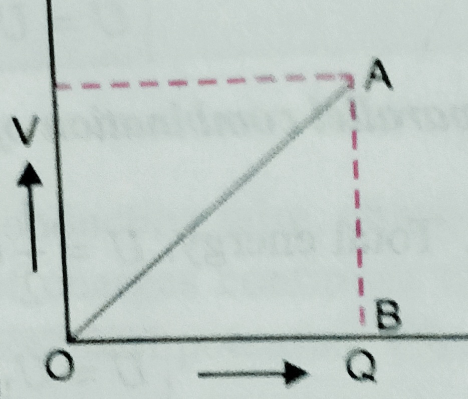
    If we plot the graph  potential v/s charge we get,


    ***Similarly we can plot the graph (i)  U v/s V ( when C is constant )

    (ii) U v/s C (when V is constant)

    (iii) U v/s V  (when Q is constant)

    Total energy stored in the combination of capacitors –

    In  series combination –  U = Q2/2CS But in series combination 1/Cs = 1/C1  + 1/C2 + 1/C3   ….

    So we can write in series combination total energy U = U1 + U2 + U3 + …..

    In parallel combination – U = ½ Cp V2 = ½ C1 V2 + ½ C2 V2 + ½ C3V2 …..

    So we can write in parallel combination total energy of the combination   U = U1+ U2 + U3 ……

    Energy density of a  parallel plate capacitor –

    Energy density of the capacitor is the energy stored per unit volume of the capacitors or condensers . We can write energy density u = U/ ( volume )

    u = ( ½ C V2 )/ A d  ( Where A is the area of the plate and D is the separation between the plates .

    But potential V = E( electric field) d  . putting this value in the above equation we get  ,

    u = ½ ( ϵ0 A /d ) ( E2 d2 / Ad ) = ½ ϵ0 E2 .

    the  unit of energy density is  J/m3 .


  • Grouping of capacitors

    Grouping of capacitors

    Grouping of capacitors

    Before to know about grouping of capacitors students should know about parallel plate capacitor .To read about the topic parallel plate capacitor click here-

    This is the topic in which students will learn about grouping of capacitors , which contain series combination and parallel combination of the capacitors .

    (Combination) Grouping of capacitors or condensers  –

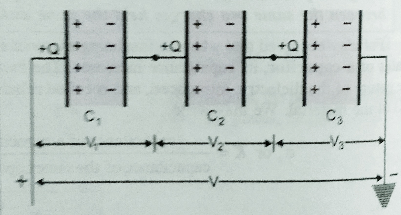
    1. Capacitors in series –   When negative plate of first capacitor is connected with positive of second , negative of second connected to positive of third and so on such combination is called series combination . in another words we can say that, the capacitors are said to be connected in series between two points , when we can proceed from one point to the other only through one path .

    As shown in figure three condensers of capacitance C1 , C2 and  C3  are connected in series .

    Suppose V is the potential difference across the combination .  Suppose   ‘Q’ charge is given to the left plate of C1 due to induction -Q charge setup on the other plates and =Q on the left plate of capacitor C2 and so on . Let V1, V2 and V3 are the potential difference setup across the capacitors  C1 , C2 and  C3  respectively . charge across the capacitors are same which is Q . Then V1 = Q/C1 , V2 = Q/C2 . V3 = Q/C3 . So net potential   V = V1 + V2 + V3 ;

    If CS is the equivalent capacitance of the combination of the capacitors then  ,

    Q/CS = Q/C1 +  Q/C2 + Q/C3

    Or ,  1/CS = 1/C1+ 1/C2 + 1/C3

    If there are n  capacitors are connected in series then

     1/CS = 1/C1+ 1/C2 + 1/C3 …………………+ 1/Cn


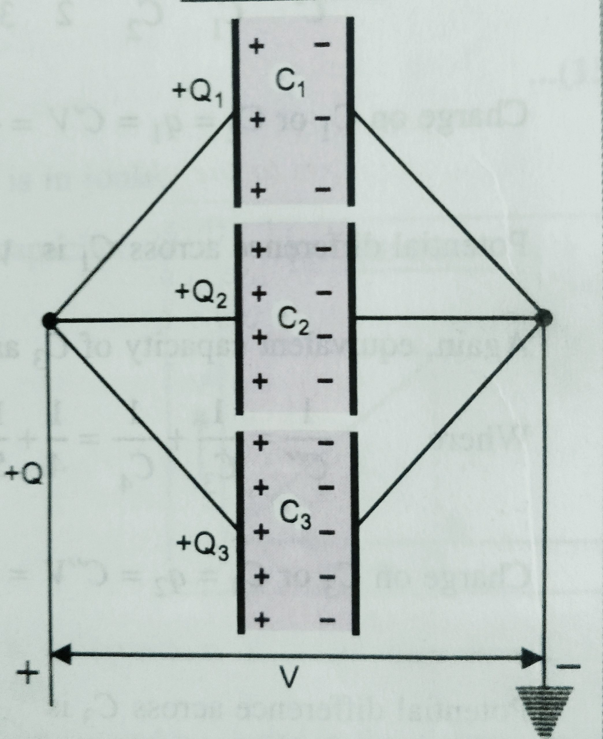
    1. Capacitors in parallel – The combination of the two or more capacitors are said to be in parallel if positive plates of capacitors are connected at one point and all negative plates at another points as shown in figure .

    Let C1 ,C2 , and C 3 are the capacitance of the three capacitors , and V is the potential difference applied across the combination . The potential difference across each capacitor is V the charge on each are Q1 Q2 and  Q3 , because their capacitance are different .  S o net charge Q = Q1 + Q2 + Q 3

    If CP is the equivalent capacitance of the capacitors then CP V =  C1 V + C2 V + C3 V

    So, Equivalent capacitance  CP  =  C1  + C2  + C3 ;

    If there are n  capacitors are connected in parallel then

    CP  =  C1  + C2  + C3……………..+ Cn


  • Parallel plate capacitor

    Parallel plate capacitor

    Parallel plate capacitor

    Before to know about these topics student must know about Electrical capacitance, To know about electrical capacitance click here-

    In this topic we will discuss about capacitance and its principle ,and expression for the capacitance of parallel plate capacitor .

    Capacitor and its principle – It is an arrangement in which large amount of  electric charge can be stored and hence develop large potential difference in small space. A capacitor consists of a system of two conductors separated by an insulating medium. Often the two conductors are charged by connecting them to the two terminals of a battery.  Or we can say that the capacitance of an insulated conductor is increased considerably by bringing near it an uncharged conductor connected to earth.

     If the conductors are plane , the capacitor is called a parallel plate capacitor , when the conductor is spherical called spherical conductor , and if the conductor is cylindrical then the capacitor is called cylindrical capacitor .

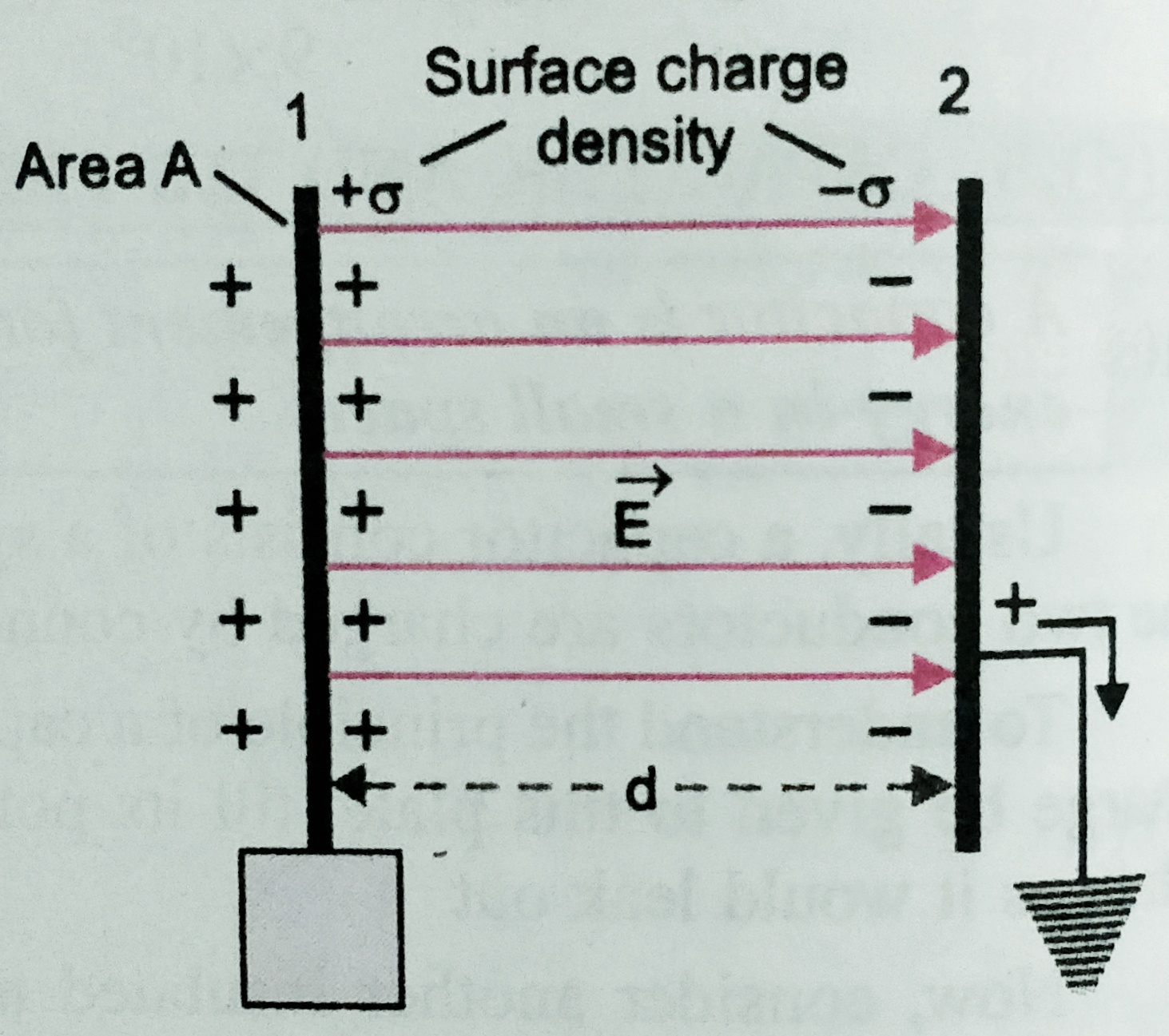
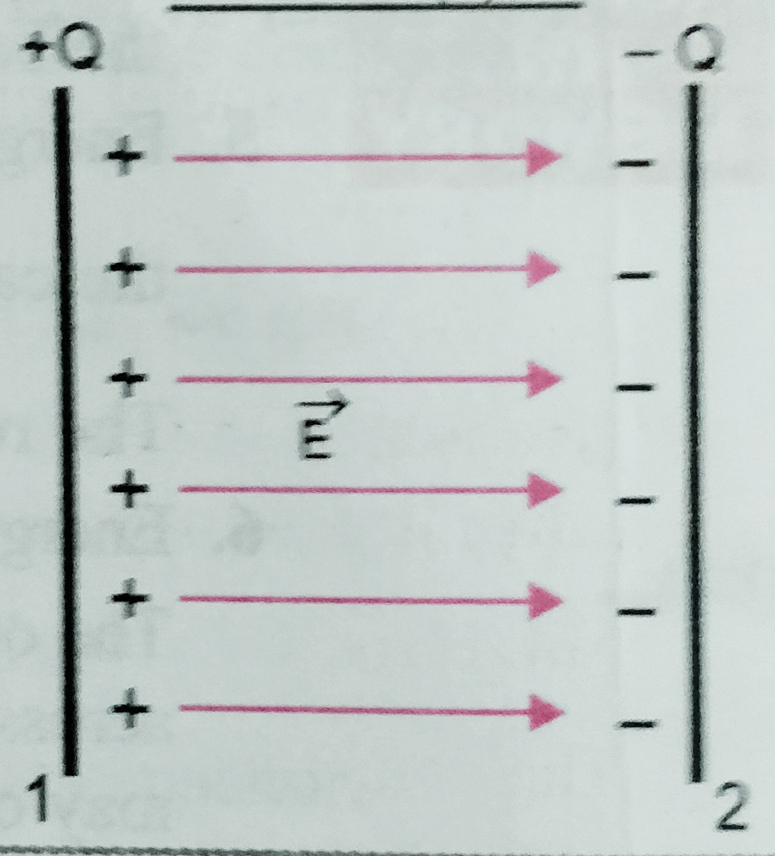
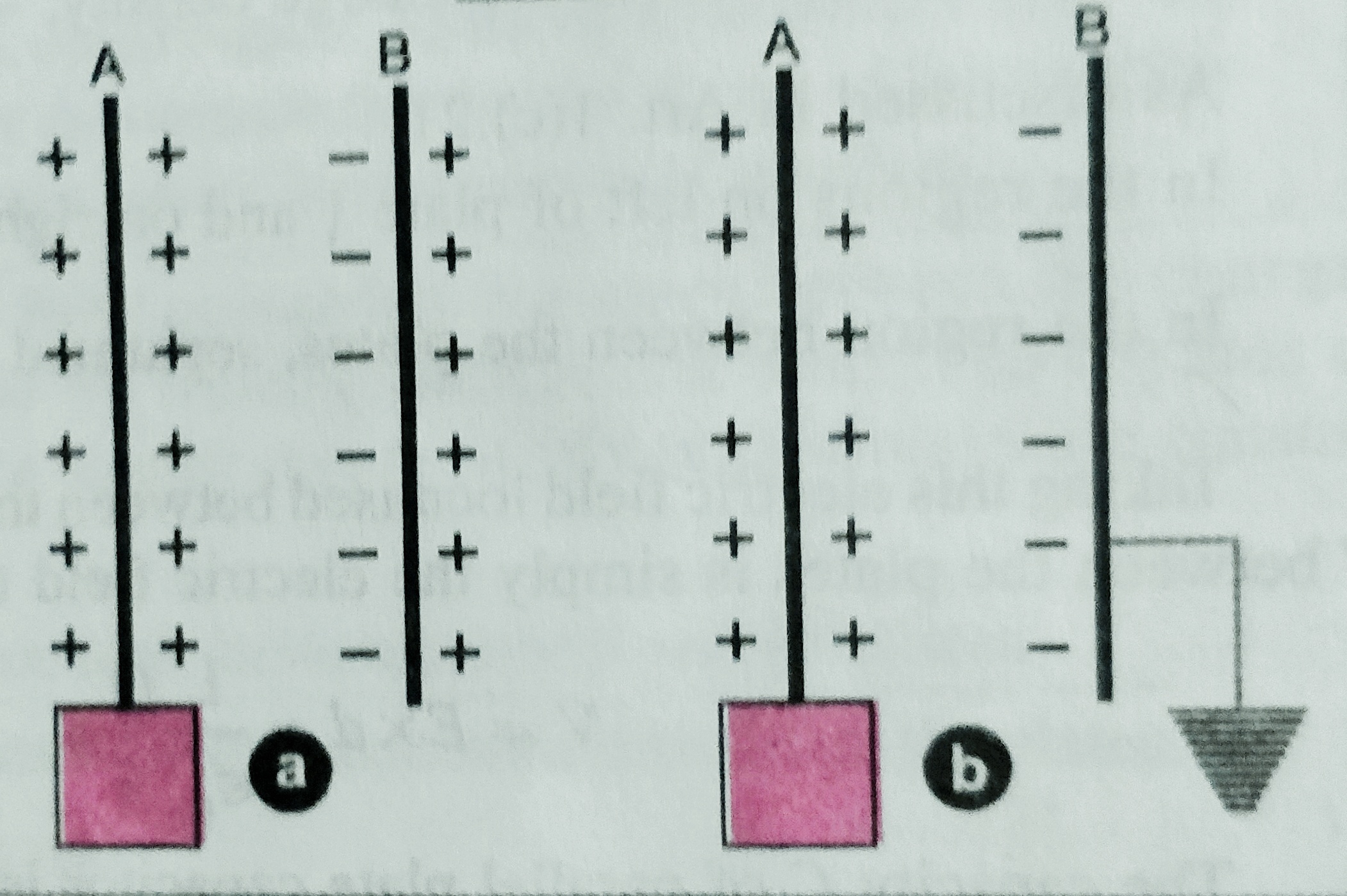
    Parallel plate capacitor – A parallel plate capacitor consists of two thin conducting plates each of plate area ‘A’  and separated by distance ‘d’ . One of the plate is insulated and the other plate is earthed .  When charge Q is given to one plate then the charge -Q is induced on the near face of the  second plate and +Q on the farther  face of the second plate , and +Q is flows to the earth .

    The surface charge density of the first plate is     +σ = Q/A

    And on the other plate is        -σ = -Q/A .

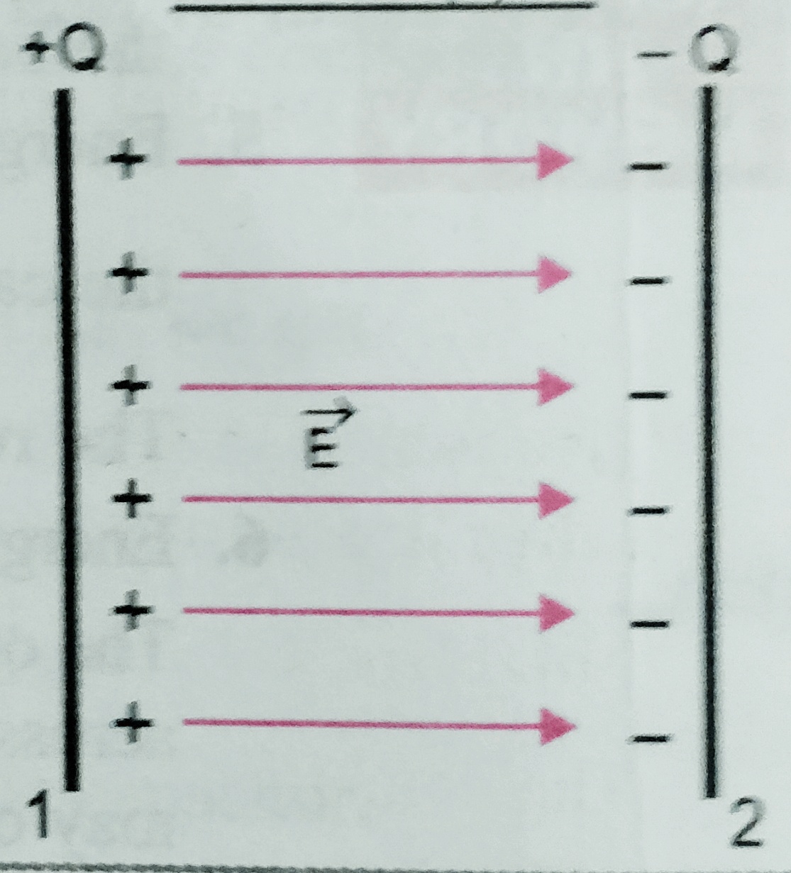
    So electric field between the plates is  E = σ/ϵ0 = Q/Aϵ0 ;

    Potential difference between the plates is V = E.d = Qd/Aϵ0 

    Hence capacity of the  capacitance will be C = Q/V = Q/( Qd/Aϵ0 ) = Aϵ0  / d   i.e . the capacitance of parallel plate capacitor is independent of the charge and potential .


  • Electrical capacitance

    Electrical capacitance

    Electrical capacitance

    In this topic we will discuss about the Electrical capacitance and electrostatics of conductor,electrostatic shielding  , and the capacity of an isolated spherical conductor .

    Electrostatics of conductor –

    As we know a conductor is a substance through which electric charge can conduct from one point to another . But there is some important results regarding  electrostatics of conductor which are follows –

    1. In electrostatic equilibrium , electric field is zero every where inside the conductor . Suppose a conductor ABCD is held in an external electric field of intensity E0 as shown in figure , the free electrons in the conductor moves from AB to CD . As a result , some net negative charge appears on AB . and the produced electric field Ep , which opposes the flow of free electrons from AB to CD . since Ep = E0 so net field inside the conductor is zero .

    1. The electric field just outside the charged conductor is perpendicular to the surface of the conductor at every point .
    2. Net charge in the interior of the conductor is zero .

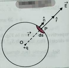
    According to Gauss’s law  ∫E.ds =q/ϵ0 ];

    since inside the conductor E=0

    therefore q= 0 also ;

    1. Electric field at the surface of the charged conductor is given as E = σ/ϵ0 where σ is the surface charge density . and the surface charge density is different at different point for irregular shaped conductor .

    ELECTROSTATIC SHIELDING –

     It is the phenomenon to protect a space or an object from external electric field by covering it by conducting substance . as we know electric field inside a conductor is zero hence when an object is placed inside the conductor then there is no electric field connected to the object which is inside the conductor .

    Electrical capacitance –

    Electrical capacitance of a conductor is the ability of the conductor to store electric charge in it.

    When conductor given some charge then its potential increases . Let Q is the charge given to the conductor then its potential increases to V volt so , we can say,   Q α V  or , Q = CV ; where C is a constant called capacity of the conductor , we can write  capacity C = Q/V  , Using this expression we can write , capacity of a conductor is the ratio of charge given to the potential developed in the conductor i.e. C = Q/V ;


    In another way we can define , electrical capacity of a conductor is numerically equal to the charge required to increase the potential by unit volt .      Its unit is farad (F)

    Here 1 Farad =1 coulomb/1 volt and its dimension is [ M-1L-2T4A2]

    CAPACITY OF AN ISOLATED SPHERICAL CONDUCTOR –

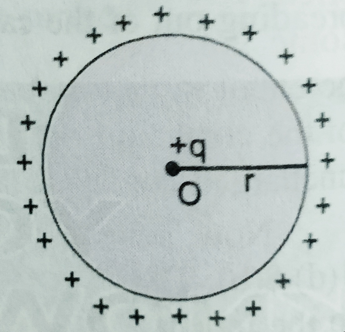
    Suppose a conductor of radius ‘r’ with centre ‘O’ has given charge ‘Q’  then its potential increases by ‘V’ . here potential V= q/4∏ϵ0r

    As we know capacity C = Q/V = Q/( q/4∏ϵ0r) Or. C = 4∏ϵ0r  ; Here r is in meter and  C is in farad .

    As we can see C α r i.e larger the radius of the sphere and larger will be capacity of the conducting sphere .

    Using this formula we can find the capacity of the earth which is given as

    C= 4×3.14 x(1/9×109) x 6.4x 106 = 711 x 10-6F  or 711μF .

    For next topic of electrostatics  which is parallel plate capacitor -click here –

  • Gauss’s law and proof of Gauss’s law.

    Gauss’s law and proof of Gauss’s law.

    Gauss’s law and proof of Gauss’s law .

    In this topic we will learn Gauss’s law , derivation of gauss’s law , derivation of coulomb’s law using gauss’s law .

    Before to know about Gauss’s law and proof of Gauss’s law student must know electrostatic flux , to read the notes on electrostatic flux click here-

    Question in the examinations may be asked as –

    state and prove Gauss’s law , using gauss’s law derive Coulomb’s law.

    Gauss’s law in electrostatics –

    According to Gauss for a closed surface total flux  in the free surface is 1/ϵ0 times the total charge inside the closed surface.

    To download the pdf of Gauss’s law and proof of Gauss’s law click here-