Tag: Magnetic effect of current

  • Motion of a charged particle in uniform magnetic field

    Motion of a charged particle in uniform magnetic field

    Motion of a charged particle in uniform magnetic field

    In this topic Motion of a charged particle in uniform magnetic field we will discuss about how a charged particle moves in uniform magnetic field, when it is projected with some velocity at an angle with magnetic field.

    Before to know about this topic students must know about the force acting on a charge particle when it moves in a uniform magnetic field. To know about this topic force on a charge particle in uniform magnetic field click here.

    Motion of a charged particle in uniform magnetic field –

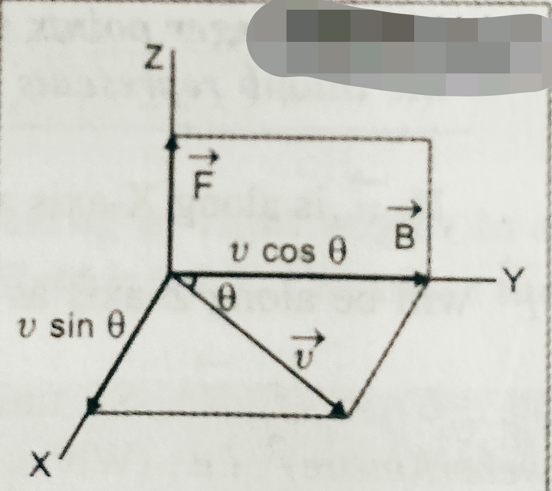
    Suppose a charged particle of mass ‘m’ and charge ‘q’ is projected  with velocity ‘v’ at angle ‘ϴ’ with the magnetic field  ‘B’ as shown in figure (a) . Here v has two components  (v1= vcosϴ ) along x -axis and ( v2= v sinϴ) along y-axis.
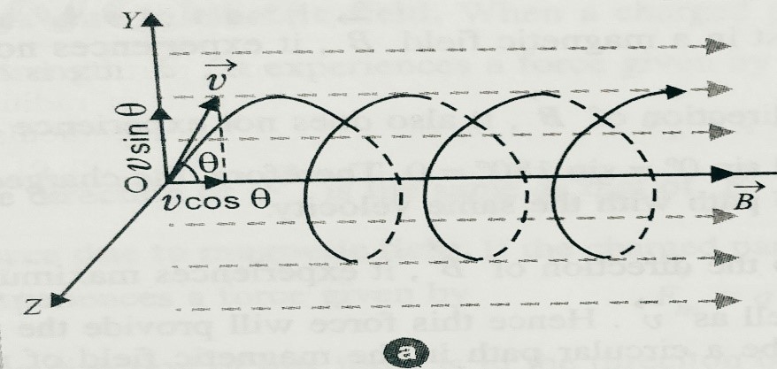
    Due to v1 it moves along x-axis and due to v2 a force F acts which is given as F = qv2 B = qvBsinϴ. Since this force F acts perpendicular to the velocity and magnitude of v2 not changes hence it moves on a circular path.  As shown in fig(b).
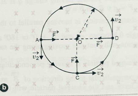
    let r is the radius of the circular path , due to these two components of v1 and v2 particle follows a helical path as shown in fig(a) .

    As we know when body moves on a circular path the centripetal forc F = mv22/r = mv2sin2ϴ/r ;

    Which is provided by magnetic force F= qvBsinϴ

    So we can write  mv2sin2ϴ/r = qvBsinϴ;

    So, r = mvsinϴ/qB ……………….(1)

    or vsinϴ=qBr/m …………………….(2)

    angular velocity  ω= vsinϴ/r = Bqr/mr = Bq/m ……………..(3)

    here frequency  f=ω/2∏ = Bq/2∏m  ( here frequency is independent of velocity)………….(4)

    and time period T = 1/f = 2∏m/Bq ……………………………(5).

    The pitch of the helix = vcosϴ x T = v cosϴ 2∏m/Bq .

    Special cases –

    Case (i) -If ϴ=00 i.e. v1=v and v2=0

    So there will be no force and particle will move in the direction of B .

    Case (ii) – if ϴ=900 then v1=0 and v2=v  i.e. body will move only in the circular path

    And radius of the circular path  r= mv/qB  or  r= v/(q/m)B .


  • Solenoid and Toroid

    Solenoid and Toroid

    Solenoid and Toroid

    Before to know Solenoid and Toroid  , students must know Ampere’s circuital law , proof of Ampere’s circuital law and its application.        To know all these thing click here-

    In this topic we will discuss about  one of the application of Ampere’s circuital law . We will define solenoid and Toroid , we will find the magnetic field due to Solenoid and Toroid .

    Solenoid –

    It is the closely wound coil in the form of helix . its length is very large as compared to its diameter.


    Magnetic field due to a solenoid –

    Let current I is flowing through the coil , each turn of solenoid regarded as a circular loop carrying current which produces a magnetic field . Total magnetic field is vector sum of magnetic field due to current through all the turns in the coil .

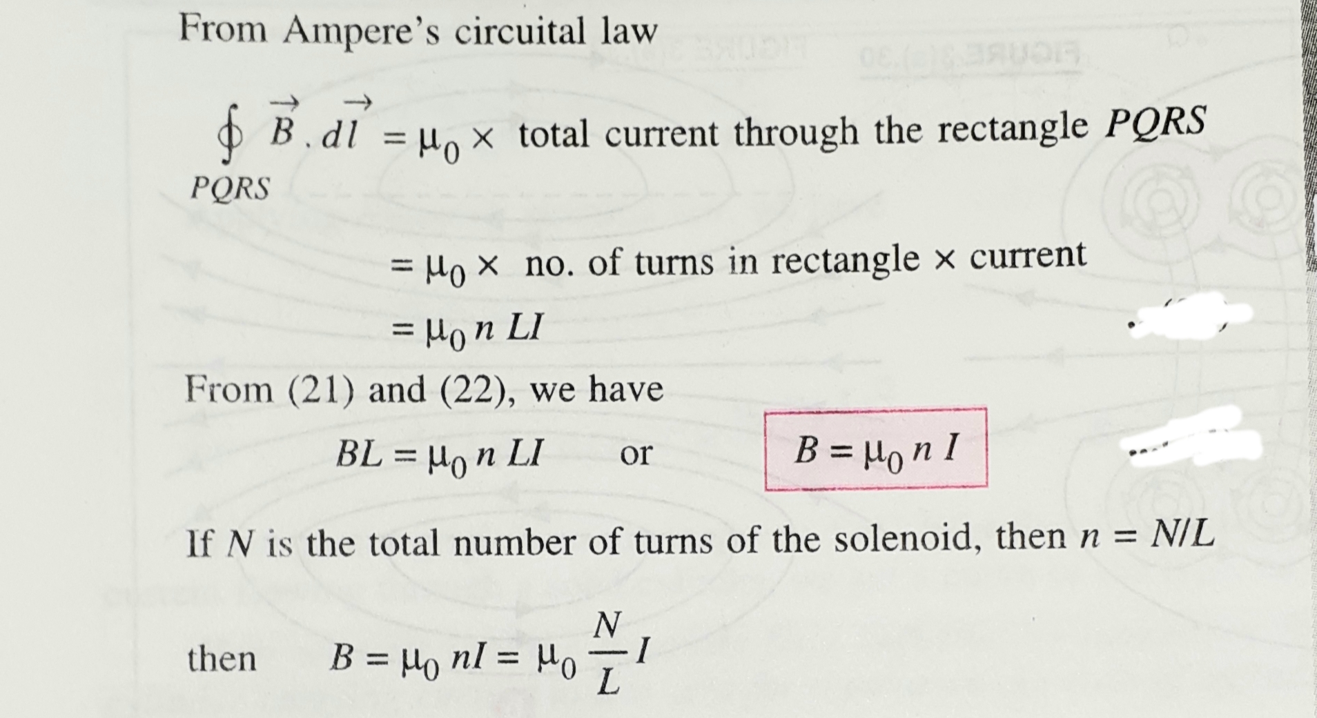
    Let n be the number of turns per unit length of the solenoid . Consider a rectangular loop PQRS  near the middle of the solenoid as shown in figure.

    PQ=L . hence total numbers of turn in length L = nL .

    The line integral of magnetic field over the closed path PQRS is ,

    At a point near the end of the solenoid magnetic field B = μ0nI/2 .

    If the solenoid is filled by material of permeability μ in side then magnetic field B = μnI = μ NI/L.

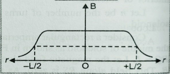
    If we draw a plot magnetic field B vs r (distance) from the centre of the solenoid we get the following curve.


    Toroid –

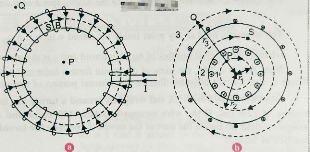
    Toroid is the endless solenoid in the form of ring . or we can define ‘The toroid is the hollow circular ring on which a large number of insulated turns of a metallic wire are closely wound’. As shown in figure below.

    Magnetic field due to current in a toroid–  Let n be the number of turns per unit length of the toroid , I be the current flowing through the toroid . When current passes through the solenoid magnetic field of constant magnitude setup in side the turn of toroid in the form of circular magnetic field . We draw three circle having radii r1,r2 and r3 as shown in fig (b). Let B1 is the magnetic field along loop 1  then using Ampere’s law –

    The magnetic field at any point inside the empty space surrounded by toroid or outside the toroid magnetic field is zero .

  • Ampere’s circuital law

    Ampere’s circuital law

    Ampere’s circuital law

    In this topic we will discuss about Ampere’s circuital law and proof of Ampere’s circuital law ( using Biot- Savart’s law).We will also discuss the  applications of  Ampere’s circuital law (Magnetic field due to infinite long straight wire carrying current,magnetic field due to current through very long circular cylinder or thick wire, solenoid and Toroid)

    Ampere’s circuital law –

    According to this law the line integral of the magnetic field around any closed path in free space is equal to μ0 times the total current passing through the surface enclosed by the closed path .

    – To download the complete notes (pdf) of Ampere’s law and proof of Ampere’s law click here–Ampere.law and its proof

    To watch the video of Ampere’s circuital law click on the link given below-

    Applications of Ampere circuital law –

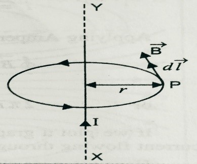
    Application(i) Magnetic field due to infinite long straight wire carrying current – To down load the notes(pdf) on this topic click on the link given here- magnetic field due to long wire

    Application (ii). Magnetic field due to long current carrying cylinder or thick wire. To download the notes(pdf) click here -Magnetic field due to long current carrying cylinder or thick wire

    Application(iii). Solenoid and Toroid-To get the notes on solenoid and toroid click here-


  • Magnetic field at a point on the axis of a circular coil carrying current

    Magnetic field at a point on the axis of a circular coil carrying current

    Magnetic field at a point on the axis of a circular coil carrying current

    Before to learn about this topic students must know about Biot-Savart law. To learn about this topic click here-

    In this topic we will discuss about Magnetic field at a point on the axis of a circular coil carrying current , and using its derivation we can find the magnetic field and we will also discuss about magnetic moment due current carrying coil.

    To get the notes on magnetic field at the center of a circular current carrying coil, click here-

    Magnetic field at a point on the axis of a circular coil carrying current –

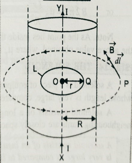
    Suppose a circular coil of radius ‘a’ with center ‘O’ . Let current I is flowing through the coil we have to find the magnetic field at point ‘P’ , which is x distance away from the center .

    Suppose two small element ‘dl’ of the coil C and D which is diametrically opposite points as shown in figure.

    Here PC =PD = √(a2+x2), and we consider <COP = ɸ = <DPO .

    As shown in figure dBcosɸ is cancelled  by each other , then the net magnetic field dB sinɸ  will be in the same side .

    Here magnetic field due to small current carrying element  dB = (µ0/4Π) I dl sinθ/r2  ; here r=√(a2+x2),

    So we can write  , dB=(µ0/4Π) Idl sinθ/(a2+x2) ,

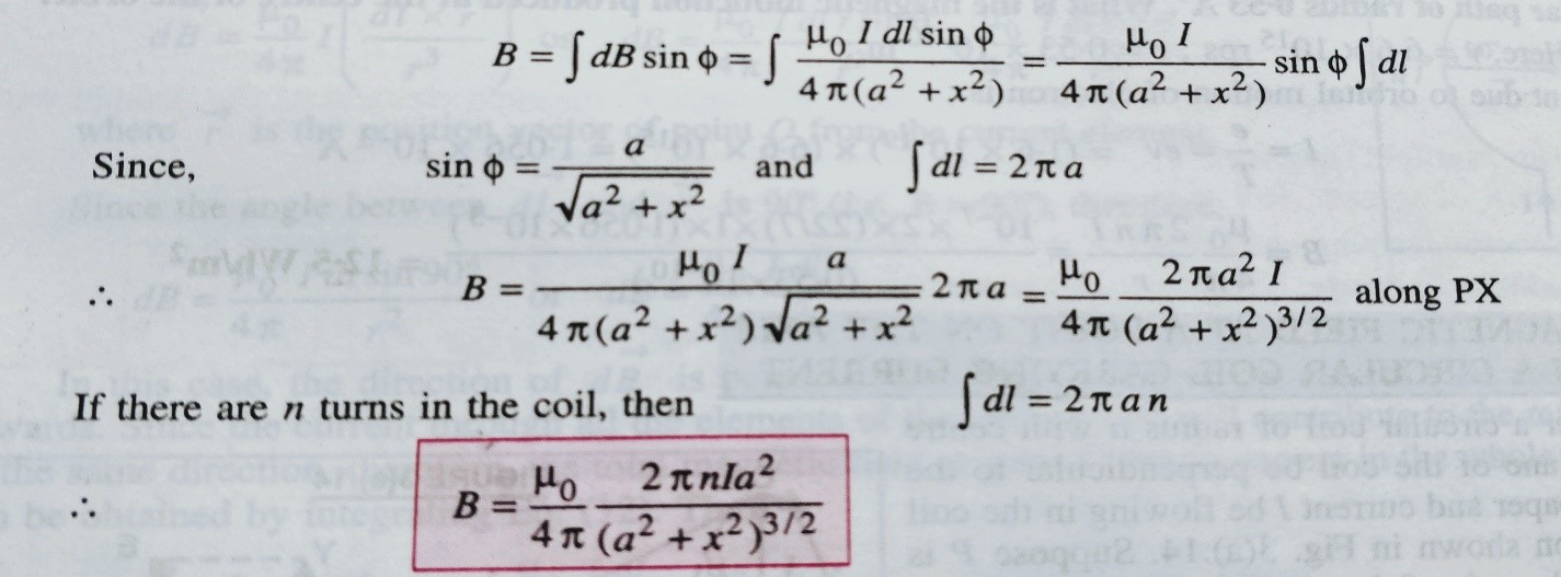
    So magnetic field at point p due to the circular loop


    Special case  1- when point P lies at the center of the circular coil then , x = 0

    Then B= (µ0/4Π)  2∏nI/a = µ0nI/2a ,

    Case 2 – When point P is far away from the center then a2+x2=x2

    Then B= (µ0/4Π)  2nIA/x3 [ since ∏a2 = A (area)]

    Here nIA= M (magnetic moment)

    So we can write , B= (µ0/4Π)  2M/x3

    So we can define the magnetic moment due to current carrying coil is given as the product of ampere turns and area of current loop . SI unit of magnetic moment is A-m2 .

    To watch the video related to this topic, Magnetic field at a point on the axis of a circular coil carrying current ( By Nayan jha sir) go to the link given below-


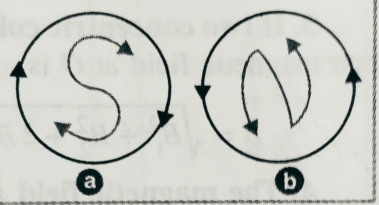
    The polarity of magnetic dipole due to the current loop is decided as , if the current from one side is clock wise direction it gives south pole and on another face direction of current is anti-clock wise it gives  north pole , as shown in figure-

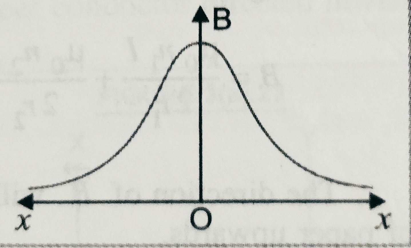
    Case 3- The variation of magnetic field induction with distance of a point on the axis of coil carrying current is given as –

    class 12th physics syllabus removed . How it is beneficial for the students , see the video given below-

  • Magnetic field at the center of a circular current carrying coil

    Magnetic field at the center of a circular current carrying coil

    Magnetic field at the center of a circular current carrying coil

    Before to know about this topic students must know Biot-Savart’s law.

    To get the notes on Biot-Savart’s law click here-

    Magnetic field at the center of a circular current carrying coil is the one of the application of Biot-Savart’s law . here we will derive the expression for Magnetic field at the center of a circular current carrying coil .

    syllabus class 12th physics (2020-2021)

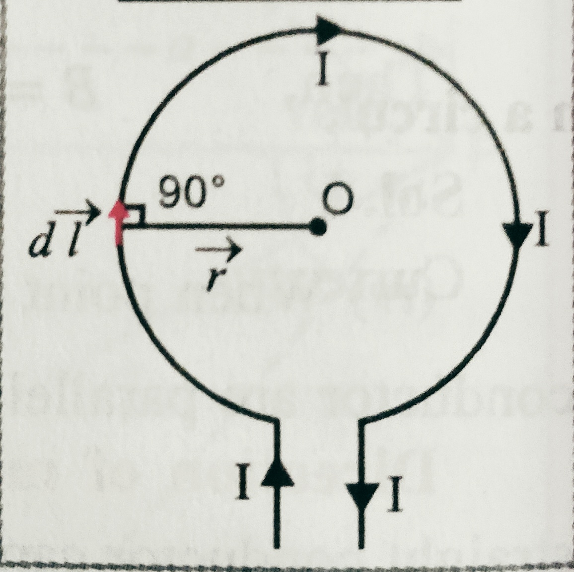
    Magnetic field at the center of a circular  current carrying coil – Consider a circular coil of radius ‘r’ having center ‘O’. suppose I be the current flowing through the coil , and we have to find the magnetic field at the center .

    Suppose a small element ‘dl’ which is the part of coil create a magnetic field dB at the center.

    According to Biot-savart’s law dB = (µ0/4Π) I dl sinθ/r2 . but ϴ=900,

    So we can write dB = (µ0/4Π) I dl sin900/r2 = dB = (µ0/4Π) I dl /r2 .

    Then magnetic field at the center due to complete coil

    B=∫ (µ0/4Π) I dl sinθ/r2 ( Taking limit 0 to 2∏)

    We get B= dB = (µ0/4Π) I 2∏r/r2  =  µ0 I /2r

    For an arc which is making angle ϴ at the center will be given as

    B= (µ0 I /4∏r)(Angle at the center )

    Or , B= (µ0 Iϴ /4∏r) ;

    The direction of magnetic field due to current carrying coil may be give by right hand rule , according to it if curled finger shows the direction of current then stretched thumb gives the direction of magnetic field .

    To watch the video of related topic click here-

    For next topic  magnetic field at a point on the axis of a circular current carrying coil . click here-

  • Force on a moving charge in a Magnetic field

    Force on a moving charge in a Magnetic field

    Force on a moving charge in a Magnetic field 

    In this topic Force on a moving charge in a Magnetic field , define the magnetic field and units and dimension of magnetic field .We will also know about Fleming’s left hand rule.

    Before to know about this topic Force on a moving charge in a Magnetic field we must learn about Oersted’s experiment and Ampere’s swimming rule. To know about this topic click here – 

    Force on a moving charge in a Magnetic field –

    Suppose a positive charge ‘q’ is moving with velocity ‘v’ at an angle ‘ϴ’ with magnetic field ‘B’. Then experimentally it is found that   force ‘F’ experienced depends on

    F α q ………(i)

    F α B……………….(ii)

    F α v sinϴ …………(iii)

    On combining these three equations we get ,

    F α q B v sinϴ

    Or, F =k q B v sinϴ ; where k is constant of proportionality k=1

    Then we can write F = q B v sinϴ or, F = q( x  )

    Here the direction of force is given by Fleming’s left hand rule or right hand screw rule .

    Fleming’s left hand rule –

     According to this rule when we stretch our left hand’s fore finger, middle finger and thumb such that they are perpendicular to each other , if fore finger shows the direction of field, middle finger shows the direction of current( +ve charge) then thumbs gives the direction of force .

     Definition of B (magnetic field intensity) –  

    As we have seen in the equation F = q B v sinϴ ;

    If  q= 1C , v=1m/s ϴ=900 i.e. sinϴ = 1 then   B= F ;

    So we can define magnetic field intensity at a point is equal to the force experienced by a unit charge moving with a unit velocity perpendicular to the direction of magnetic field at that point .

    Unit of  magnetic field ‘B’ –

    From the equation F = q B v sinϴ ,

    B = F/qv sinϴ ; then unit of B is NA-1m-1 = Tesla  (T) ,

    And dimension of B is [M A-1 T-2]


  • Magnetic effect of current,Oersted experiment and Amperes swimming rule

    Magnetic effect of current,Oersted experiment and Amperes swimming rule

    Magnetic effect of current, Oersted experiment and Amperes swimming rule –

    In this topic we will discuss about magnetic effect of current,Oersted experiment and Ampere’s swimming rule.

    Magnetic effect of current–

    When electric current passes through a conductor (conducting wire) then magnetic field developed around the conductor.

    The intimate relationship between electricity and magnetism was discovered 200 years ago , Oersted discovered in the year 1820 that a straight wire carrying current cause a deflection in a nearby magnetic compass needle.


    Oersted’s experiment and Ampere’s swimming rule-

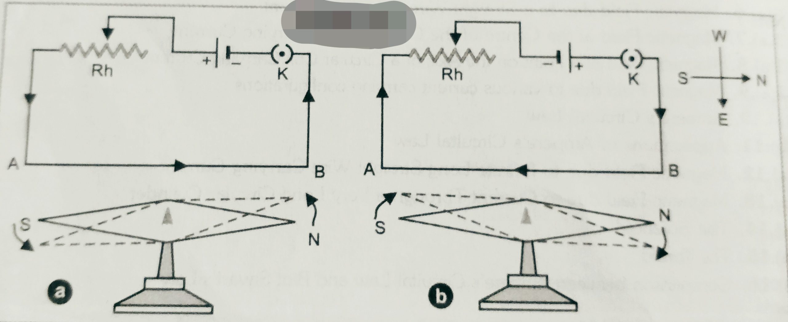
    According to Oersted’s experiment , we take a needle NS which is free to rotate . We place the needle above a current carrying wire AB . If current flows through the wire in the direction A to B   and from B to A then deflection in the needle shown in the figure . Since magnetic needle can deflect only in the interaction of the another magnetic field . so it is confirmed that due to flow of current in a conductor magnetic field setup across around the wire.

    The direction of deflection in the magnetic needle due to current in the wire is given by Ampere swimming rule . According to this rule ‘ If a man swimming along the wire in the direction of current with his face turned always towards the needle , so that the current  enters through his feet and leaves in his had , then north pole of the magnetic needle will be deflected towards his left hand’ .


  • Objective questions of magnetism and matter

    Objective questions of magnetism and matter

    Objective questions of magnetism and matter

    This assignment contains all type objective questions of magnetism and matter. it will be helpful for the students preparing for class 12th board examination or other competitive examinations like JEE/ NEET .

    Magnetism and matter

    1. With the tangent galvanometer it is desirable to have a deflection near 45°; then the percentage error:
    • (a)is less in the reading of deflection
    • (b)is negligible in the reading of deflection
    • (c)is less in the measurement of current
    • (d)is large in the measurement of current
    1. The sensitivity of a moving coil galvanometer depends on:
    • (a)the angle of deflection
    • (b)the earth’s magnetic field
    • (c)torsional constant of the spring
    • (d)the moment of inertia of the coil
    1. An ammeter can be converted into a voltmeter by connecting:
    • (a)a high resistance in series
    • (b)a low resistance in parallel
    • (c)a low resistance in series
    • (d)a high resistance in parallel
    1. In a moving coil galvanometer the deflection of the coil θ is related to the electric current I by the relation:
    • (a)I ꭀ tan θ       (b) I ꭀ θ                   (c) I ꭀ θ2                      (d) I ꭀ √θ
    1. A voltmeter of range 2V and resistance 300 Ω cannot be converted into ammeter of range:
    • (a)1 A      (b) 1 mA             (c) 100 mA              (d) 10 mA
    1. The effect due to uniform magnetic field on a freely suspended magnetic needle is as follows:
    • (a)both torque and net force are present
    • (b)torque is present but no net force
    • (c)both torque and net force are absent
    • (d)net force is present but not torque
    1. A voltmeter has a resistance of G ohm and range V volt. The value of resistance used in series to convert it into voltmeter of range nV volt is:
    • (a)nG       (b) (n – 1)G               (c) G/n                   (d) G/(n – 1)
    1. An ammeter has a resistance of G ohm and a range of I The value of resistance used in parallel to convert it into an ammeter of range nI amp is:
    • (a)nG       (b) (n – 1)G               (c) G/n               (d) G/(n – 1)
    1. To reduce the range of a voltmeter, its resistance need to be reduced. Which of the following resistance when connected in parallel will convert it into a voltmeter of range (V/n)?
    • (a)nR0 (b) (n + 1)R0     (c) (n – 1)R0        (d) None of these

    To download entire  assignment click here- Magnetism and matter objective


  • Objective questions of magnetic effect of current

    Objective questions of magnetic effect of current

    Objective questions of magnetic effect of current

    this assignment contains all important objective type  questions of  magnetic effect of current . Students preparing for 12th board examination or other competitive examination  like JEE/NEET.

    Before to solve objective questions of this chapter student may solve the objective questions of electric current. To download assignment of objective questions of electric current click here- 

    1. Magnetic induction is measured in:
    •  (a)weber (b) weber/m     (c) weber/m2      (d) weber/m3
    1. The force acting on a charge q moving with a velocity ʋ in a magnetic field of induction B is given by:
    • (a) q/(ʋ ₓ B) (b) (ʋ ₓ B)/q      (c) q/(ʋ ₓ B)         (d) (ʋ . B)q
    1. Two free parallel wire carrying currents in the opposite directions:
    • (a)attract each other
    • (b)repel each other
    • (c)do not affect each other
    • (d)get rotated to be perpendicular to each other
    1. Two parallel wires carrying currents in the same direction attract each other because of:
    • (a)potential difference between them
    • (b)mutual inductance between them
    • (c)electric forces between them
    • (d)magnetic force between them
    1. A free charged particle moves through a magnetic field. The particle may undergo a change in:
    • (a)speed  (b)energy   (c) direction of motion  (d) none these
    1. An electron and a proton travel with equal speeds and in the same direction, at 90° to a uniform magnetic field. They experience forces which are initially:
  • MOVING COIL GALVANOMETER

    MOVING COIL GALVANOMETER

    In moving coil galvanometer we will learn about the working theory of a galvanometer and its conversion from galvanometer to ammeter and voltmeter

    To read the complete topic click here- Moving Coil Galvanometer